Stepping laser welding device for welding resistance wires

A laser welding, step-by-step technology, used in laser welding equipment, welding/welding/cutting items, auxiliary devices, etc., can solve the problems of weak solder joints, unstable resistance value, etc. The effect of stable value, ensuring robustness and reliability

Pending Publication Date: 2020-06-09
北京凯米迈克科技有限公司
View PDF0 Cites 0 Cited by
  • Summary
  • Abstract
  • Description
  • Claims
  • Application Information

AI Technical Summary

Problems solved by technology

[0003] In view of this, the present invention provides a step-by-step laser welding device for welding resistance wires, which solves the key problems of weak solder joints and unstable resistance values, and improves welding speed and production efficiency at the same time

Method used


Image

  • Stepping laser welding device for welding resistance wires
  • Stepping laser welding device for welding resistance wires
  • Stepping laser welding device for welding resistance wires

Examples


Embodiment Construction

[0025] The present invention will be described in detail below with reference to the accompanying drawings and examples.

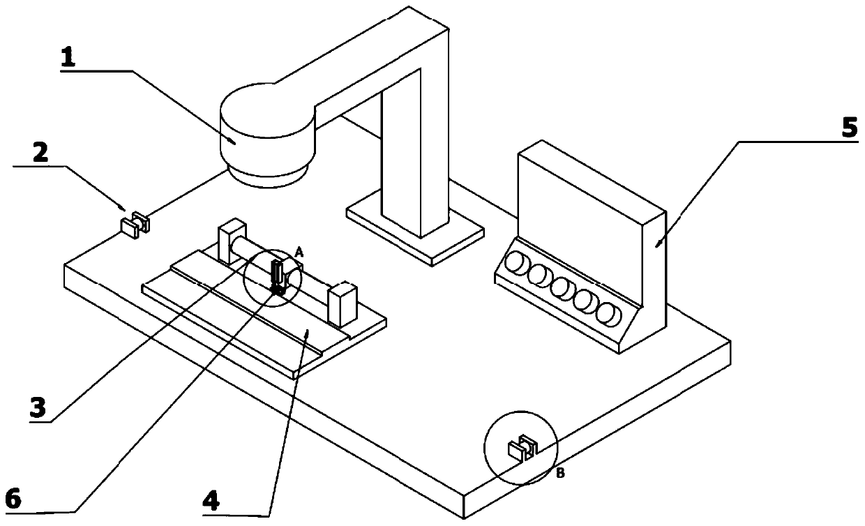
[0026] This embodiment provides a step-by-step laser welding device for welding resistance wires, such as image 3 As shown, it includes a laser welding machine 1, a vibrating mirror, a feeding guide device 2, a stepping feeding cylinder 3, a welding backing plate 4, a controller 5 and a clamping device 6.

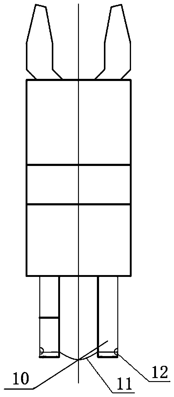
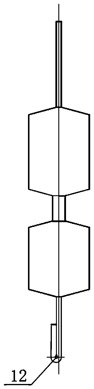
[0027] The welding object is the electrode frame belt, such as figure 1 , figure 2 As shown, the same end of the two electrodes clamps the same resistance wire 11 to form an electrode frame 10, and the electrode frame 10 formed on the base material along the straight line is the electrode frame belt; the clamping place 12 of the resistance wire is the part to be welded . The base material is copper alloy, or tin-plated copper alloy, or nickel-copper alloy, or carbon steel, or / and stainless steel; when the base material is a strip, the thickness ran...


PUM

PropertyMeasurementUnit
thicknessaaaaaaaaaa

Abstract

The invention provides a stepping laser welding device for welding resistance wires. The stepping laser welding device for welding resistance wires comprises a laser welding machine, a galvanometer, afeeding guide device, a stepping feeding cylinder, a clamping device, a welding backing plate and a controller, wherein a welding object is an electrode frame strip; the controller is used for setting welding parameters and stepping feeding speed parameters of the laser welding machine; a to-be-welded section of the electrode frame strip is positioned on the welding backing plate, the clamping end of an electrode frame is positioned at the focus below the galvanometer, and the laser output by a welding laser machine is modulated by the galvanometer and then sequentially irradiates the clamping end of the electrode frame to weld the resistance wire to the electrode frame; and the clamping device moves forward under the driving of the stepping feeding cylinder after clamps the electrode frame strip, and meanwhile, the next section of the electrode frame strip is continuously fed into the range of the welding backing plate under the action of the feeding guide device. The stepping laserwelding device for welding resistance wires solves the key problems of weak welding spots and unstable resistance value, and improves the welding speed and the production efficiency.

Description

technical field [0001] The invention relates to the technical field of pyrotechnics and civil blasting equipment production, in particular to a step-by-step laser welding device for welding resistance wires. Background technique [0002] At present, the welding method and technology commonly used in the welding technology of nickel-chromium resistance wire (or called resistance wire) in the production process of electric pyrotechnic products, rigid electric pyrotechnic heads, and flexible electric pyrotechnic heads is: the electrode frame is first pressed Bending, then including the resistance wire in the bend, or attaching the resistance wire to the end face of the electrode frame, and then using argon arc welding, or energy storage resistance welding, or tin welding to connect the folded electrode frame back to its background Welding together, the resistance wire is clamped between the two, instead of welding the electrode frame and the resistance wire into one. In the lo...

Claims


Application Information

Patent Timeline
Patent Type & Authority Applications(China)
IPC IPC(8): B23K26/22B23K26/70B23K37/04
CPCB23K26/22B23K26/702B23K37/0443B23K2101/32B23K2101/38B23K2103/04B23K2103/05B23K2103/12
Inventor 柳勤李明安张理农李纯荣张连壮
Owner 北京凯米迈克科技有限公司
Why Eureka
Try Eureka