
Fast and efficient self-adaptive optical compensation stimulated Raman scattering imaging system and method

A technology of stimulated Raman scattering and adaptive optics, applied in Raman scattering, laser utilizing scattering effect, optics, etc., can solve the problem of time-consuming spatial light modulator, etc., achieve fast adaptive beam focus compensation, light intensity Improve and overcome slow effects

Active Publication Date: 2020-05-29
ZHEJIANG UNIV
View PDF7 Cites 10 Cited by
  • Summary
  • Abstract
  • Description
  • Claims
  • Application Information

AI Technical Summary

Problems solved by technology

[0008] In order to solve the problems existing in the background technology, the purpose of the present invention is to propose a fast and efficient adaptive optical compensation stimulated Raman scattering imaging system and method, which uses a deformable mirror with a high image refresh rate to solve the problems traditionally used in biomedicine The problem of time-consuming spatial light modulator in adaptive optics

Method used


Image

  • Fast and efficient self-adaptive optical compensation stimulated Raman scattering imaging system and method
  • Fast and efficient self-adaptive optical compensation stimulated Raman scattering imaging system and method
  • Fast and efficient self-adaptive optical compensation stimulated Raman scattering imaging system and method

Examples


Embodiment Construction

[0043] The present invention will be further described below in conjunction with accompanying drawing and example.

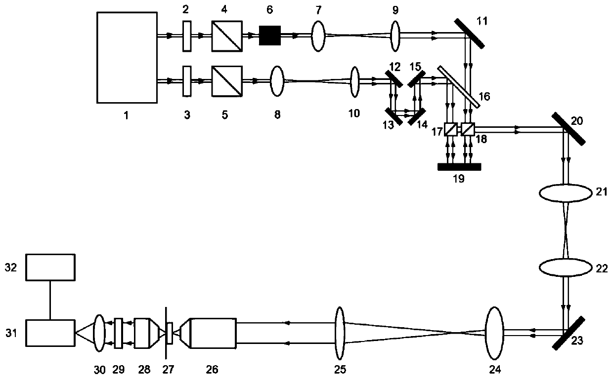
[0044] Such as figure 1 As shown, the specific implementation includes laser 1, half-wave plates 2, 3, polarization beam splitter 4, 5, acousto-optic modulator 6, beam expander module, mirror 11, dichroic mirror 16, phase delay module, beam combiner module, deformable mirror 19, scanning module, microscope objective lens 26, experimental sample 27 and light intensity detection module; two half-wave plates 2, 3 and two polarization beam splitters 4, 5 are arranged in front of the output end of the laser 1, The laser emits two beams of different wavelengths, and the two beams are adjusted to the same polarization direction through their respective half-wave plates 2, 3 and polarizing beam splitters 4, 5. The first beam is transmitted from the polarizing beam splitter 4, 5 after being emitted by the acousto-optic modulator 6 and the beam expander module to enter t...


PUM


Abstract

The invention discloses a fast and efficient self-adaptive optical compensation stimulated Raman scattering imaging system and method. According to the system, two half-wave plates and a polarizing beam splitter are arranged in front of an output end of a laser, the laser emits two beams, both of the beams pass through the half-wave plate and the polarizing beam splitter, the first beam sequentially enters a reflector through an acousto-optic modulator and a beam expanding module, the second beam enters a dichroic mirror after passing through the beam expanding module and a phase delaying module; after reflection, the second beam transmitted by a dichroic mirror and reflected by a dichroic mirror is combined and incident to two regions of a deformable mirror at intervals and reflected intoa beam, the reflected beam is focused by a scanning module incident microscope objective lens, and the scattered beam generated by transmission of an experimental sample is received and detected. According to the system and method, compensation phase value of the deformable mirror is optimally adjusted, so that a focusing light spot with stronger central light intensity can be formed in a sampleafter the beam is subjected to phase compensation, so that nonlinear effect can be better excited, and imaging quality at a deep position in a scattering medium is improved.

Description

technical field [0001] The invention belongs to an optical compensation scattering imaging system and method in the field of optical microscopic imaging, in particular to a fast and efficient adaptive optical compensation stimulated Raman scattering imaging system and method, and is applied to non-invasive deep penetration Label-free light microscopy imaging. Background technique [0002] In the field of biomedical optics, optical scattering is the main factor restricting the quality of optical imaging. Most optical techniques for deep tissue imaging (eg, confocal laser imaging, two-photon microscopy, and optical coherence tomography) primarily utilize non-scattered photons (ie, ballistic photons) for imaging. The number of ballistic photons decays exponentially with depth, thus limiting the optical focus range to a depth of 1 mm. [0003] The adaptive optics technology, which was previously applied in astronomy, provides new technical support for deep biological tissue im...

Claims


Application Information

Patent Timeline
Patent Type & Authority Applications(China)
IPC IPC(8): A61B5/00G01N21/01G01N21/65G02F1/35H01S3/30
CPCA61B5/0075A61B5/0033G01N21/658G01N21/01G02F1/35H01S3/30G01N2021/0112Y02A90/10
Inventor 龚薇斯科李政翰张德龙
Owner ZHEJIANG UNIV
Learn More