Automatic gain control system and method for active phase scanning ground reconnaissance radar

A technology of automatic gain control and gain control, applied in radio wave measurement systems, instruments, etc., can solve problems such as receiver saturation, signal distortion, interference, etc., to improve detection performance and reduce false alarm probability.

Pending Publication Date: 2020-05-19
NANJING UNIV OF SCI & TECH
View PDF5 Cites 6 Cited by
  • Summary
  • Abstract
  • Description
  • Claims
  • Application Information

AI Technical Summary

Problems solved by technology

[0003] In the active phase-scanned ground radar, the target echo is submerged by the echo of strong ground objects. When the antenna beam points to the direction of strong ground objects, it will cause the receiver to be saturated, and the signal entering the AD module of the signal processing board will be distorted, resulting in interference, False alarms, target detection performance degradation
At present, when the receiver gain of the conventional active phase-scan ground radar is updated every scanning cycle, most of them are fixed gain control or manual gain control. A fixed gain is built into the software, and the receiver gain is judged manually during the work process. Whether it needs to be adjusted, but under manual gain control, the echo amplitude in all directions cannot be kept near the maximum unsaturated peak-peak value of AD. If the echo is attenuated too small, the AD performance will not be fully utilized, and it will affect the radar detection performance, resulting in Target detection probability drops
When the ground environment changes, there will inevitably be a situation where the set gain does not match the current environment. The user cannot accurately judge the current echo intensity, and cannot quantitatively determine the appropriate gain.

Method used


Image

  • Automatic gain control system and method for active phase scanning ground reconnaissance radar
  • Automatic gain control system and method for active phase scanning ground reconnaissance radar
  • Automatic gain control system and method for active phase scanning ground reconnaissance radar

Examples


Embodiment

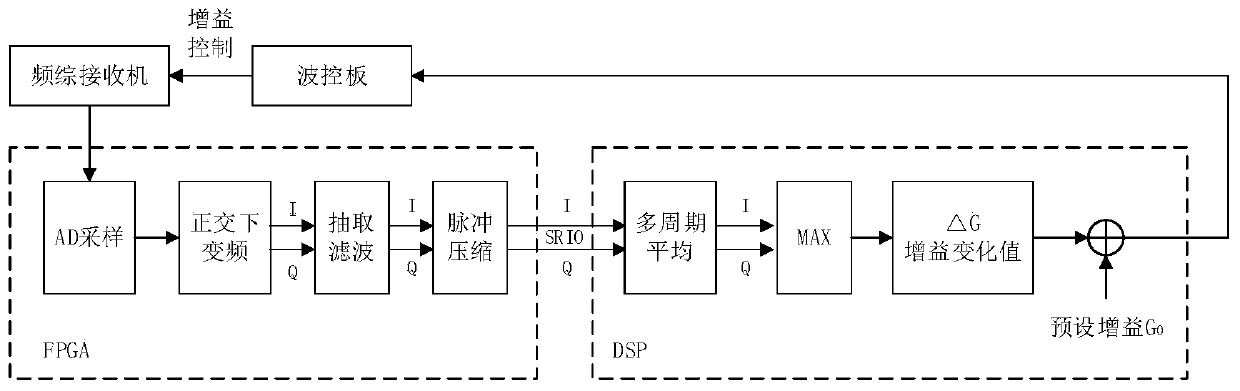
[0075] In the ground feature measurement mode, the ground feature strength estimation and automatic gain control code calculation and storage are performed. Let the transmitted signal be a 2-pulse combination waveform, and the signal duration is t T1 =0.5us,t T2 =20us, the receiving time is t respectively R1 =29.5us,t R2 =100us, from which the effective receiving time is intercepted as t' R1 = 16.67us, t' R2 =83.33us, signal bandwidth B=30MHz, pulse repetition cycle number M A =100, sampling frequency f of intermediate frequency echo s = 80MHz, extraction multiple D = 8 / 3, the data rate after extraction is 30MSPS, then the points of I and Q after pulse 1 and pulse 2 are respectively N 1 = 500 and N 2 =2500. The pulse pressure processed data is transmitted to DSP through SRIO to estimate the intensity of ground features and calculate the receiver gain control code. combine image 3 , the implementation steps of the automatic gain control system are as follows:

[007...


PUM


Abstract

The invention discloses an automatic gain control system and method for an active phase scanning ground reconnaissance radar. The system comprises an array antenna, a T / R assembly, a frequency synthesizer receiver, a wave control board, an electronic compass and a signal processing unit. The amplitude characteristics of fixed ground object echoes under different wave beam orientations in a radar scanning range after intermediate frequency digitization, down-conversion decimation filtering, pulse compression and the like are measured by presetting the receiver gain, and a receiver gain controlcode in each direction is determined, thereby realizing an automatic gain control system for adaptively adjusting the receiver gain along with the change of the ground object environment where the radar is located. The receiver gain can be adaptively adjusted according to the ground object echo power when the antenna beam points to different orientations so that overflow distortion of strong ground object orientation echo sampling is ensured not to occur and weak ground object orientation echo cannot be attenuated, the quantization performance of the AD chip can be fully utilized, the detection performance of the radar can be enhanced and the false alarm probability can be reduced.

Description

technical field [0001] The invention belongs to the field of digital signal processing of active phase-sweeping ground reconnaissance radar, in particular to an automatic gain control system and method of active phase-sweeping ground reconnaissance radar. Background technique [0002] Active phased array technology has flexible and rapid beam pointing; multiple independent beams can be formed at the same time, and comprehensive functions such as target search, tracking, identification, and passive detection can be realized; high reliability, even if a small number of transmitting / receiving units fail, it can still work normally It has been widely used in the field of ground activity target reconnaissance. The ground reconnaissance radar works in a strong ground clutter environment, and strong ground clutter echoes can easily cause receiver saturation. The time sensitivity (STC) control technology commonly used in pulse compression radars cannot solve the large ground echo in...

Claims


Application Information

Patent Timeline
IPC IPC(8): G01S7/34G01S7/292
CPCG01S7/34G01S7/2927Y02A90/10
Inventor 谢仁宏王丽妍李鹏芮义斌郭山红孙泽渝边晨光吕宁王欢
Owner NANJING UNIV OF SCI & TECH
Why Eureka
Try Eureka