
An integrated cooker without oil fume emission

A technology of no oil fume and cooking utensils, applied in the direction of removing oil fume, household stoves, household appliances, etc., can solve the problems of incomplete separation of oil fume, secondary pollution of the environment, etc., achieve simple structure, reduce production cost, and improve reliability

Active Publication Date: 2021-07-27
韩波
View PDF12 Cites 0 Cited by
  • Summary
  • Abstract
  • Description
  • Claims
  • Application Information

AI Technical Summary

Problems solved by technology

[0003] The purpose of the present invention is to solve the problem that the existing integrated cookers generally have incomplete oil fume separation, need to set up a special oil fume exhaust channel and easily cause secondary pollution to the environment, and design a kind of oil fume exhaust channel that can also be used without damaging the environment. Pollution-free smoke-free integrated cooker

Method used


Image

  • An integrated cooker without oil fume emission
  • An integrated cooker without oil fume emission
  • An integrated cooker without oil fume emission

Examples


Embodiment 1

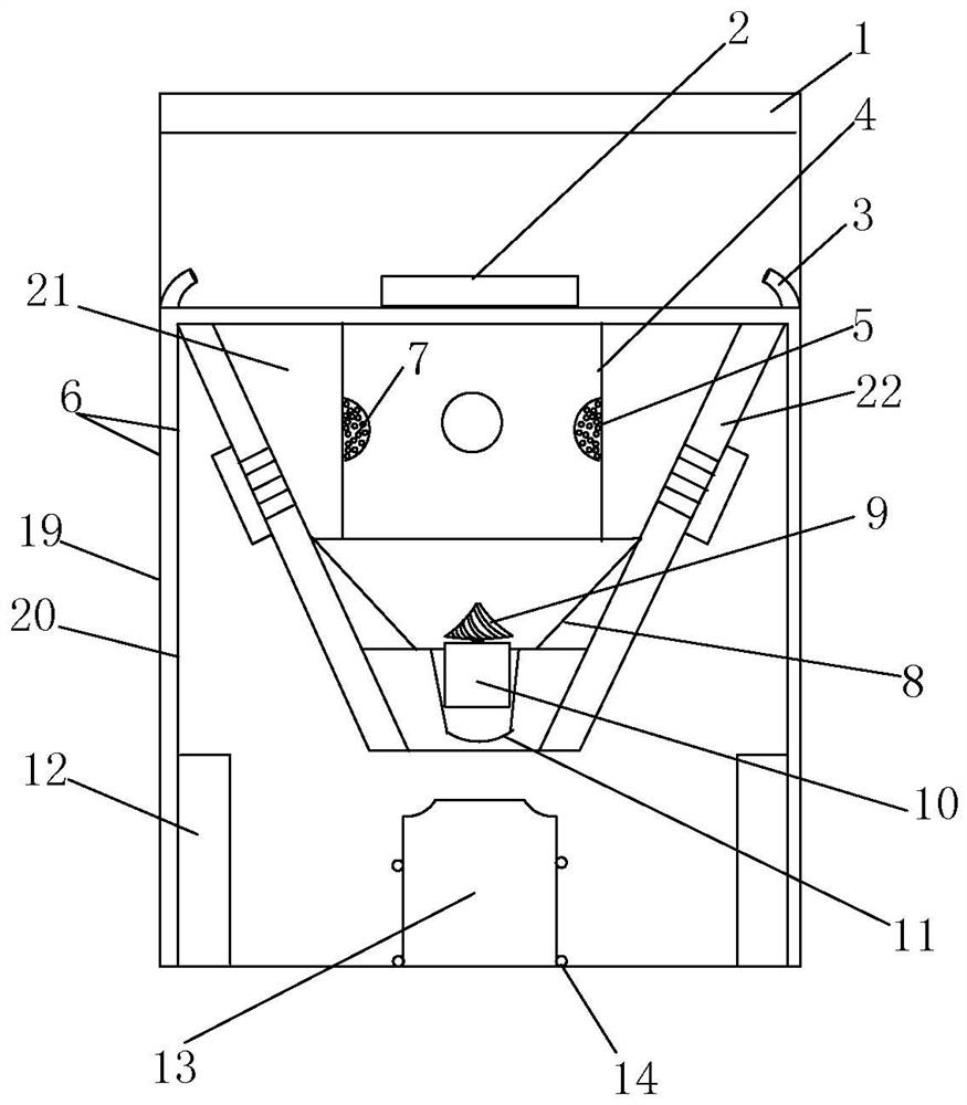
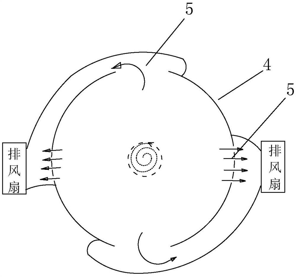
[0027] Such as Figure 1-3 shown.

[0028] An integrated cooking range without oil fume discharge, which includes a housing 6, the upper part of the housing 6 is provided with an air inlet 1, such as figure 2 As shown, the cooking head 2 is installed on the table top of the casing 6, and the inner air duct body 4 is installed in the lower part of the cooking head 2 and the housing 6, and the positive pressure forming the central negative pressure is symmetrically arranged on the inner air duct body 4. The air outlet 5 and the positive pressure air outlet 5 are equipped with a positive pressure exhaust fan. The positive pressure exhaust fan sucks the cooking fume generated by the stove into the inner air duct body 4. Under the action of the positive pressure exhaust fan, the center of the inner air duct body 4 forms a A negative pressure chamber, and under the action of the rotation binding force (tornado rotation binding), the separation of oil, water and smoke is realized. ...

Embodiment 2

[0033] Such as Figure 5 shown.

[0034]The difference between this embodiment and Embodiment 1 is that the oil fumes are in the upper row structure, the waste oil thrown out by the oil thrower is introduced into the waste oil collection container 13 through the oil guide pipe 24, and the smoke in the upper row is filtered by the filter installed on the upper part and then discharged. . The rest are the same or similar to Embodiment 1 and will not be repeated.


PUM


Abstract

An integrated cooker without oil fume discharge, which includes a shell (6), the upper part of the shell (6) is provided with an air inlet (1), and it is characterized in that the lower part of the cooker (2) and the middle of the shell (6) The inner air duct body (4) is installed, and the positive pressure exhaust outlet (5) forming the central negative pressure is symmetrically arranged on the inner air duct body (4), and the outer side of the inner air duct body (4) is provided with an air guide duct (21 And the smoke guide air duct (22), the oily particles in the negative pressure chamber in the center of the inner air duct body (4) spin down quickly; the lower part of the inner air duct body (4) is connected with an inverted tapered outflow channel (8) , an oil thrower (9) is installed in the inverted cone-shaped outflow channel (8), and the oily particles produced by the center separation of the inner air channel body (4) fall on the oil thrower (9) through the inner air channel body (4) and It flows into the waste oil container (13) installed at the inner bottom of the shell along the inner wall of the inverted cone-shaped outflow channel (8), and a filter element for filtering smoke to achieve zero emission is installed on the inner wall of the lower part of the shell (6) ( 12).The invention has simple structure, convenient manufacture, installation and maintenance, and can realize no pollution and zero discharge.

Description

technical field [0001] The invention relates to a kitchen equipment, in particular to an integrated cooker which can be used in a place without an exhaust duct, in particular to an integrated cooker without oil fume discharge. Background technique [0002] Generally speaking, in existing urban residences, the kitchen and the living room are in the same space, and the cooking fume produced by the kitchen becomes an invisible killer. The first range hood was produced by the Swiss Franke Company during World War II. Now there are various range hoods. The principle and main structure of the range hood have not changed much. The exhaust fan rotates at the far end of the range hood to suck the air. The gas at the near end of the oil fume cavity makes the near end a negative pressure area, and the oil fume reaches the exhaust fan through the negative pressure area, and is stirred by the fan blade to make the oil fume discharge. There will be more and more oil stains on the fan bla...

Claims


Application Information

Patent Timeline
Patent Type & Authority Patents(China)
IPC IPC(8): F24C15/20
CPCF24C15/2035
Inventor 韩波
Owner 韩波
Learn More