
Paper pulp molding forming machine

A molding machine and pulp molding technology, used in textiles and papermaking, can solve the problems of high gas consumption, pollution of pulp preparation, waste of time, etc., and achieve the effects of improving accuracy and stability, solving pollution problems, and reducing production costs.

Active Publication Date: 2015-08-12
ZHEJIANG SHURCON MFG
View PDF7 Cites 8 Cited by
  • Summary
  • Abstract
  • Description
  • Claims
  • Application Information

AI Technical Summary

Problems solved by technology

Specifically, the pulp molding machine works at a temperature of about 150°C to 300°C when it is pressurized and shaped, which will reduce the service life of the seals and cause leakage and pollution of hydraulic oil.
This is particularly serious for the pulp molding machines that need to produce and prepare food packaging products, and there are serious environmental protection risks.
For this reason, strict inspection and measures to limit operation are required, which makes the management cost high
[0005] The pulp molding machine driven by the gas-liquid booster cylinder consumes a lot of gas during use, that is, high energy consumption, and because the booster cylinder contains hydraulic oil, there will also be hydraulic oil leakage. And then lead to polluted pulp preparation; moreover, the pneumatic cylinder is not easy to control, one work step is needed, and one work step is carried out sequentially, so time is wasted, that is to say, the overall work efficiency of the pulp molding machine is reduced

Method used


Image

  • Paper pulp molding forming machine
  • Paper pulp molding forming machine
  • Paper pulp molding forming machine

Examples


Embodiment Construction

[0028] In order to make the object, technical solution and advantages of the present invention clearer, the present invention will be further described in detail below in conjunction with the accompanying drawings and embodiments. It should be understood that the specific embodiments described here are only used to explain the present invention, not to limit the present invention.

[0029] In the description of the present invention, it needs to be understood that "the first servo motor" and "the second servo motor", "the first reducer" and "the second reducer", and the "first guide ventilation rod" and "the second Guide ventilation rod", and "first ball screw" and "second ball screw" are for the convenience of describing the present invention and simplifying the description, rather than referring to the specific motor, reducer, guide ventilation rod that the pulp molding machine has. rod and ball screw. In addition, the idioms "first" and "second" are used for descriptive pu...


PUM


Abstract

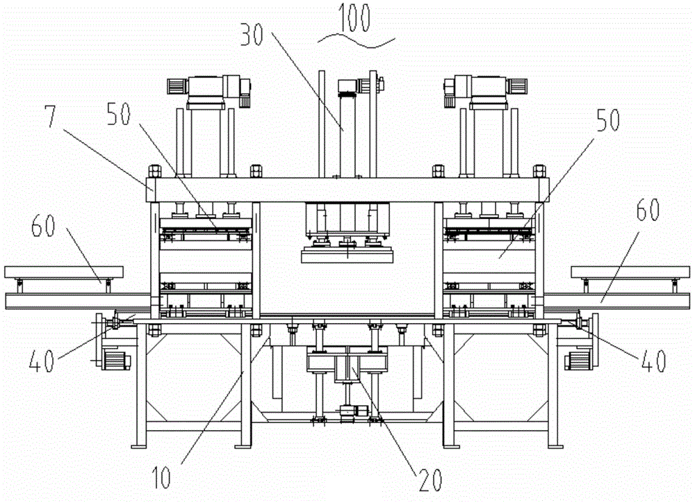
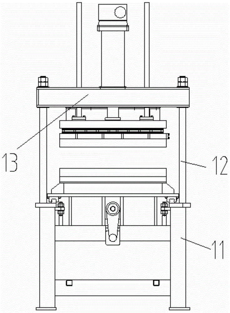
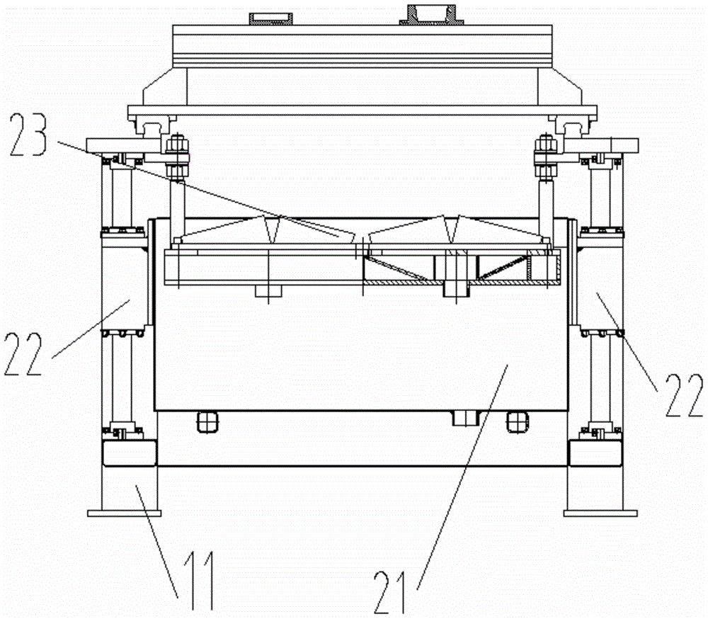
The invention discloses a paper pulp molding forming machine, comprising a machine body and a paper pulp slot lifting mechanism, a transfer die mechanism, a lower die moving mechanism, an upper die pressing down mechanism and a collecting mechanism which are arranged on the machine body; the paper pulp slot lifting mechanism is used for forming a paper pulp box; the transfer die mechanism is used for transferring the paper pulp box formed in the paper pulp slot lifting mechanism to the lower die moving mechanism; the lower die moving mechanism is used for sending the paper pulp box to the position of the upper die pressing down mechanism and is matched with the upper die pressing down mechanism to press and shape the paper pulp box; the upper die pressing down mechanism comprises an upper die assembly and a servo pressure cylinder for driving a lower die assembly to move up and down, and the servo pressure cylinder is of a mechanism drive structure. Mechanical drive is adopted, and the problem of pollution caused by hydraulic drive in the prior art is fundamentally solved; the precision and stability during work of the paper pulp molding forming machine are improved and the production cost is reduced while the production efficiency is improved.

Description

technical field [0001] The invention belongs to the technical field of mechanical equipment manufacturing, and in particular relates to a pulp molding machine. Background technique [0002] Pulp molded products are molded in the state of pulp by using molds. It can produce complex-shaped and precise pulp boxes, which have been widely used as packaging protective products and have good development prospects. [0003] At present, the existing equipment for forming pulp boxes is generally controlled by electro-hydraulic and pneumatic methods, especially for the control method of pressurization and shaping, the control method is hydraulic or gas-hydraulic booster cylinder. Driven. There are many problems in the use of the pulp molding machine controlled by these two methods. [0004] For pulp molding machines driven by hydraulic pressure, the existence of hydraulic oil has the possibility of causing pollution to the pulp that needs to be prepared when the pulp molding machine ...

Claims


Application Information

Patent Timeline
IPC IPC(8): D21J3/10
Inventor 王小建
Owner ZHEJIANG SHURCON MFG
Learn More