
Vacuum insulator with composite structure and preparation method thereof

A technology of vacuum insulation and composite structure, which is applied to insulators, electrical components, circuits, etc., can solve the problems of limited rise in vacuum surface flashover voltage, low voltage stability of insulators, and difficulty in meeting the needs of miniaturization of insulators. Inhibit the desorption process, low pressure stability, and improve the effect of flashover pressure resistance

Active Publication Date: 2020-05-15
NORTHWEST INST OF NUCLEAR TECH
View PDF12 Cites 0 Cited by
  • Summary
  • Abstract
  • Description
  • Claims
  • Application Information

AI Technical Summary

Problems solved by technology

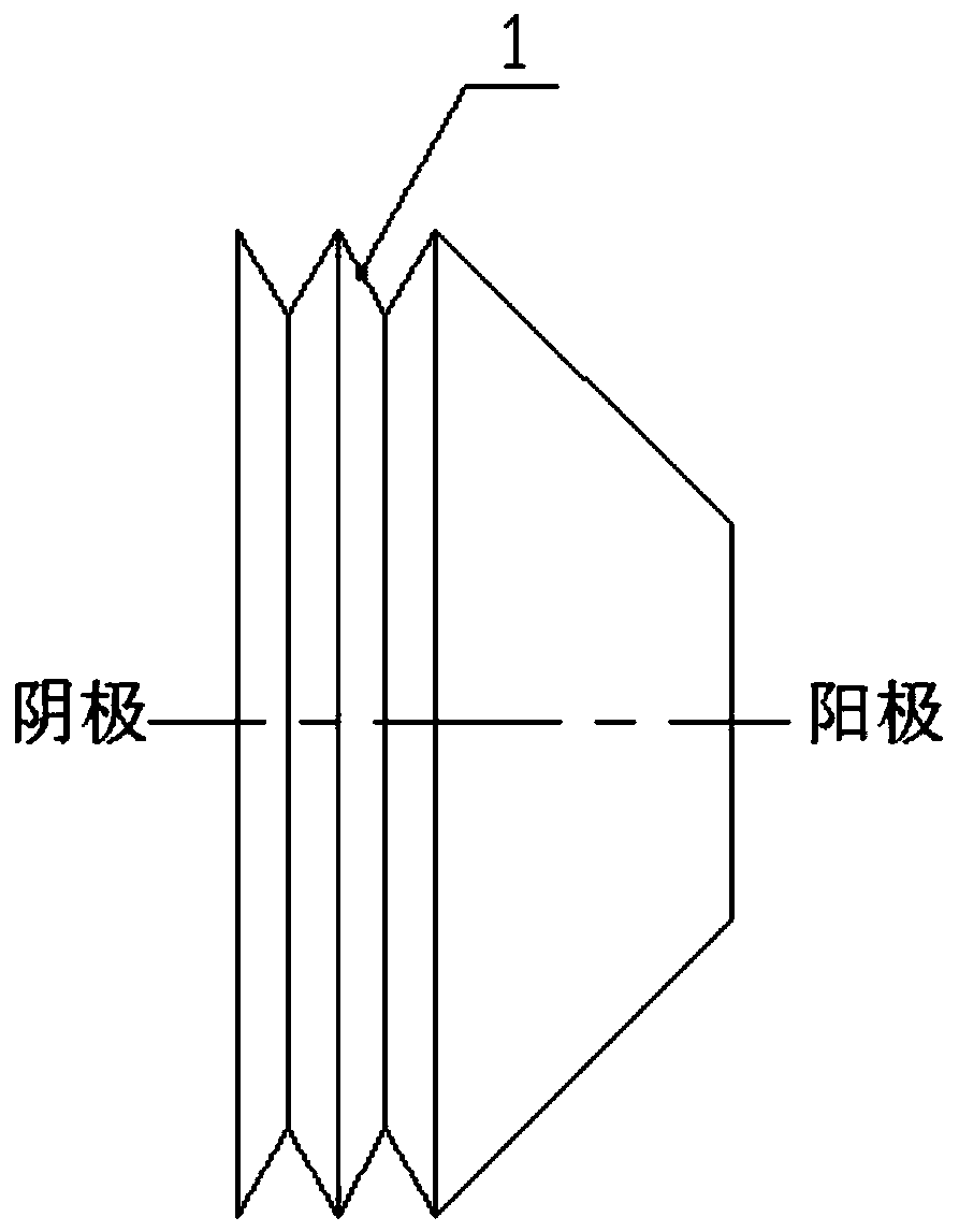
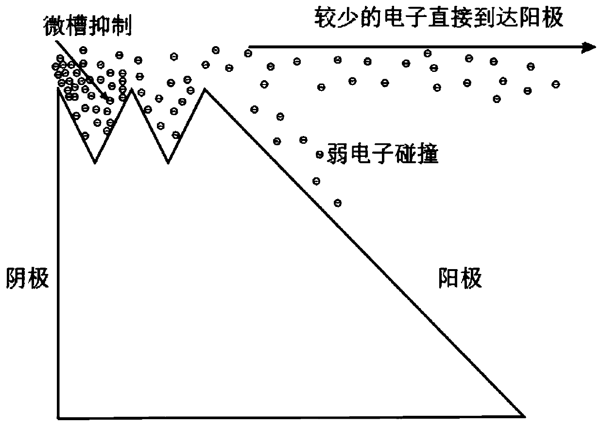
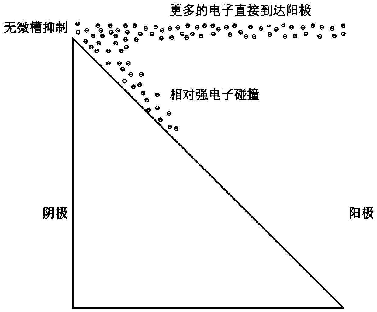
[0005] The purpose of the present invention is to provide a vacuum insulator with a composite structure and its preparation method, to solve the problem of limited increase in vacuum flashover voltage along the surface when the existing 45° inclination angle structure on the insulator surface or the micro-groove construction technology on the insulator surface is used alone, and When the 45° inclination angle structure on the surface of the insulator is used alone, it is difficult to meet the requirements of miniaturization of the insulator and the technical problem of low voltage stability of the insulator

Method used


Image

  • Vacuum insulator with composite structure and preparation method thereof
  • Vacuum insulator with composite structure and preparation method thereof
  • Vacuum insulator with composite structure and preparation method thereof

Examples


preparation example Construction

[0041] see Figure 4 , the present invention also provides a method for preparing a vacuum insulator with a composite structure, comprising the following steps:

[0042] Step 1: Prepare an insulator whose overall shape is cylindrical according to the material and size requirements of the vacuum insulator with a composite structure to be prepared;

[0043] Step 2: Process the other end of the insulator prepared in step 1 to be connected to the anode into a truncated conical shape, and the included angle between the truncated conical busbar and the bottom surface of the large end of the truncated conical shape is 30° to 60°;

[0044] Step 3: Select the laser according to the material of the vacuum insulator with a composite structure to be prepared in step 1; turn on the laser, and process the width, depth and periodic size of the microgroove 1 according to the cylindrical side of the vacuum insulator with a composite structure to be prepared , set the laser parameters; by lase...

Embodiment 1

[0050] (1) Polymethyl methacrylate (PMMA) was selected as the experimental material, and an insulator with a cylindrical overall shape was prepared by mechanical processing. The diameter of the cylindrical shape was 30 mm, and the overall height was 5 mm;

[0051] (2) the insulator prepared in step 1 is used to process the other end connected with the anode into a truncated cone shape, the included angle between the busbar of the truncated cone shape and the bottom surface of the large end of the truncated cone shape is 60°, and the height of the truncated cone shape is 3mm;

[0052] (3) Select CO 2 Infrared laser (wavelength 10.64μm), turn on the laser, set the laser parameters, and etch two ring micro-coaxial with the cylinder on the side of the cylindrical end of the above-mentioned processed frustum-shaped insulator by laser rotary etching. Groove 1, two annular micro-grooves 1 are arranged in a periodic array along the axis of the cylinder, the cross-sectional shape of th...

Embodiment 2

[0055] (1) Polyetherimide (PEI) was selected as the experimental material, and an insulator with a cylindrical overall shape was prepared by mechanical processing. The diameter of the cylindrical shape was 30 mm, and the overall height was 5 mm;

[0056] (2) The insulator prepared in step 1 is used to process the other end connected to the anode into a truncated cone shape, the included angle between the busbar of the truncated cone shape and the bottom surface of the large end of the truncated cone shape is 30°, and the height of the truncated cone shape is 4.5mm;

[0057] (3) Select the ultraviolet laser, turn on the laser, set the laser parameters, and etch 25 ring-shaped micro-shaped coaxial with the cylinder on the side of the cylindrical end of the above-mentioned processed frustum-shaped insulator by laser rotary etching. Groove 1, 25 annular micro-grooves 1 are arranged in a periodic array along the axis of the cylinder. The cross-sectional shape of the micro-groove 1 i...


PUM

PropertyMeasurementUnit
angleaaaaaaaaaa
widthaaaaaaaaaa
depthaaaaaaaaaa

Abstract

The invention relates to a vacuum insulator and a preparation method thereof, in particular to a vacuum insulator with a composite structure and a preparation method thereof. The problems that in theprior art, when an insulator surface 45-degree inclination angle structure or an insulator surface micro-groove construction technology is independently used, the vacuum surface flashover voltage increasing amplitude is limited, when the insulator surface 45-degree inclination angle structure is independently used, the requirement for miniaturization of the insulator is difficult to meet, and thevoltage-withstanding stability of the insulator is low are solved. The insulator comprises an insulator body. The insulator is characterized in that one end, used for being connected with a cathode, of the insulator body is cylindrical, the other end, used for being connected with an anode, of the insulator body is in a circular truncated cone shape, and the outer circle of the large-end bottom surface of the circular truncated cone coincides with the outer circle of the cylindrical bottom surface; a plurality of annular micro grooves which are coaxial with the cylinder are formed in the sidesurface of the cylinder; the multiple annular microgrooves are arranged in a periodic array in the cylindrical axis direction, and the array extends to the bottom face of the large end of the circulartruncated cone shape. The included angle between the circular-truncated-cone-shaped generatrix and the bottom face of the circular-truncated-cone-shaped large end ranges from 30 degrees to 60 degrees.

Description

technical field [0001] The invention relates to a vacuum insulator and a preparation method thereof, in particular to a vacuum insulator with a composite structure and a preparation method thereof. Background technique [0002] Vacuum surface flashover is a breakdown discharge phenomenon that occurs along the interface between the insulator and the vacuum. The breakdown voltage is much lower than the breakdown voltage of the vacuum and the insulator, so that the withstand voltage strength of the entire insulation system is finally determined by the vacuum surface breakdown of the insulator. Voltage is determined, which seriously reduces the withstand voltage strength of the entire vacuum insulation system [Miller H C.Flashover ofinsulators in vacuum: the last twenty years[J].IEEE Transactions on Dielectrics&Electrical Insulation.2016,22(6):3641-3657.] . With the development of high-power pulse systems in the direction of high power, high voltage, and miniaturization, the re...

Claims


Application Information

Patent Timeline
Patent Type & Authority Applications(China)
IPC IPC(8): H01B17/42H01B19/00
CPCH01B17/42H01B19/00
Inventor 刘文元霍艳坤柯昌凤陈昌华孙钧梁天学张贝
Owner NORTHWEST INST OF NUCLEAR TECH
Learn More