A high-energy sparse CT detector, CT detection system and detection method

A detector and high-energy technology, applied in the field of CT detection, can solve the problems of high cost of CT detection devices, inability to guarantee imaging accuracy, unfavorable equipment promotion and application, etc., and achieve the effects of small windmill artifacts, small row spacing, and reduced equipment costs

Active Publication Date: 2020-12-04
BEIJING HANGXING MACHINERY MFG CO LTD
View PDF7 Cites 0 Cited by
  • Summary
  • Abstract
  • Description
  • Claims
  • Application Information

AI Technical Summary

Problems solved by technology

[0005] In view of the above analysis, the present invention aims to provide a high-energy sparse CT detector, CT detection system and detection method to solve the problems of high cost of CT detection devices, which is not conducive to the popularization and application of equipment, and the imaging accuracy cannot be guaranteed due to cost reduction.

Method used


Image

  • A high-energy sparse CT detector, CT detection system and detection method
  • A high-energy sparse CT detector, CT detection system and detection method
  • A high-energy sparse CT detector, CT detection system and detection method

Examples


Embodiment 1

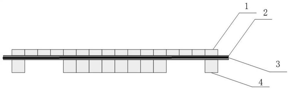
[0103] A CT detector is provided with 24 rows of low-energy detectors with a row spacing of 6mm;; There are 12 rows of high-energy detectors, all of which are arranged in a centralized way, and are arranged in the middle of low-energy detectors, with a row spacing of 6mm.

Embodiment 2

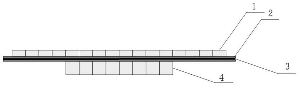
[0108] A CT detector is provided with 16 rows of low-energy detectors, and the center distance between two adjacent rows of low-energy detectors is 6mm;. There are 10 rows of high-energy detectors, of which 8 rows are arranged in a concentrated way and set in the middle of the low-energy detectors, while the other two rows of high-energy detectors are set on both sides of the detectors, and the center distance between them and the nearest high-energy detectors is 24mm.

Embodiment 3

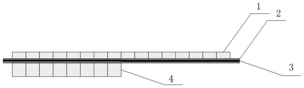
[0113] A CT detector is provided with 16 rows of low-energy detectors, and the center distance between the two rows of low-energy detectors is 6mm;. There are 8 rows of high-energy detectors, which are arranged in a centralized way and arranged at one side of low-energy detectors.


PUM

PropertyMeasurementUnit
thicknessaaaaaaaaaa

Abstract

The invention discloses a high-energy sparse CT (computed tomography) detector, a CT detection system and a detection method, belongs to the technical field of CT detection, and solves the problems that a CT detection device in the prior art is high in cost, not beneficial to popularization and application of equipment, low in cost, incapable of ensuring imaging precision and the like. The CT detector comprises high-energy detectors and low-energy detectors, the high-energy detectors and the low-energy detectors are arranged in a back-to-back mode, and one low-energy detector is arranged aboveeach high-energy detector; the number of rows of the low-energy detectors is larger than the number of rows of the high-energy detectors, and at least part of the high-energy detectors are distributed in a centralized mode. Part of high-energy detectors of the CT detector are arranged in a centralized mode, the cost is reduced, and meanwhile the imaging precision is high.

Description

Technical field [0001] The invention belongs to the technical field of CT detection, in particular to a high-energy sparse CT detector, a CT detection system and a detection method. technical background [0002] Among the explosive inspection technologies based on X-ray, X-ray computed tomography (CT) is highly valued in the field of safety inspection because of its unique advantages. The only EDS(Explosive DetectionSystem) security inspection equipment certified by TSA (Transportation Security Administration) is CT equipment, which shows the position of X-ray CT technology in the field of security inspection. [0003] X-ray CT security inspection technology is to reconstruct the CT data to obtain the tomographic image of the scanned object, and to realize the identification of dangerous goods in the scanned object by analyzing the characteristic data in the tomographic image. In order to improve the accuracy of CT identification, dual-energy CT imaging is usually adopted. Dual-e...

Claims


Application Information

Patent Timeline
Patent Type & Authority Patents(China)
IPC IPC(8): G01N23/046G01T1/20G01T1/29
CPCG01N23/046G01T1/2018G01T1/2985
Inventor 徐圆飞李保磊莫阳孙兴宏赵雷
Owner BEIJING HANGXING MACHINERY MFG CO LTD
Why Eureka
Try Eureka