Counter-force support structure for longitudinal dragging construction of steel beam and using method thereof

A technology of reaction force support and steel pipe support, which is applied in the direction of infrastructure engineering, bridges, bridge construction, etc., can solve the problems of too many pulling equipment and difficulty in ensuring the stroke maintenance of pulling equipment, and achieve clear force, continuity and displacement synchronization Sex, the effect of reducing the number of rows

Active Publication Date: 2021-04-02
CHINA RAILWAY MAJOR BRIDGE ENG GRP CO LTD
View PDF6 Cites 0 Cited by
  • Summary
  • Abstract
  • Description
  • Claims
  • Application Information

AI Technical Summary

Problems solved by technology

This method requires a lot of pulling equipment, and it is difficult to ensure that the stroke of the pulling equipment on the slideway next to each pier is maintained when the steel beam is pulled.

Method used


Image

  • Counter-force support structure for longitudinal dragging construction of steel beam and using method thereof
  • Counter-force support structure for longitudinal dragging construction of steel beam and using method thereof
  • Counter-force support structure for longitudinal dragging construction of steel beam and using method thereof

Examples


Embodiment 1

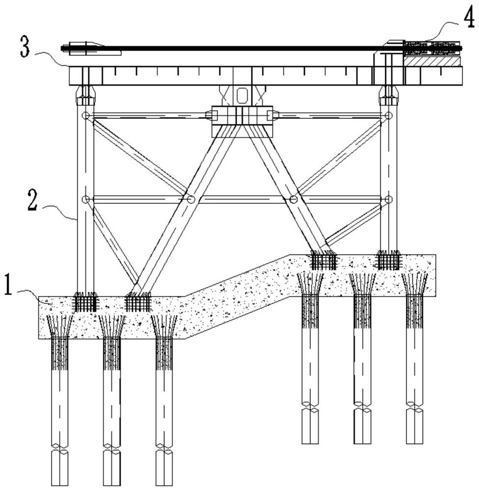
[0076] see Figure 1-9 As shown, the embodiment of the present application provides a reaction force support structure for steel beam longitudinal dragging construction, the reaction force support structure includes:

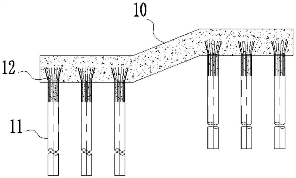
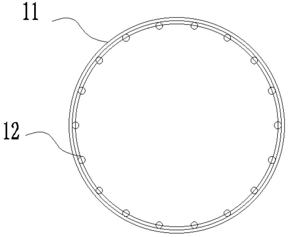
[0077] Foundation cap 1;

[0078] A plurality of steel pipe supports 2 arranged in pairs on the top surface of the foundation cap 1;

[0079] The slideway beam 3 arranged on the top surface of the steel pipe support 2;

[0080] The dragging system 4 arranged on one side of the top surface of the slideway beam 3, the dragging system 4 is used to drag the steel beam to be replaced on the top surface of the slideway beam 3; wherein,

[0081] The foundation cap 1 is a driven steel pipe pile foundation structure;

[0082] The steel pipe support 2 includes a vertical column structure and an inclined column structure.

[0083] In the embodiment of the present application, the steel pipe pile foundation and the cap are integrated to replace the traditional bored pil...

Embodiment 2

[0124] The embodiment of the present application provides a construction method of a reaction force support structure for steel beam longitudinal dragging construction, which is based on the reaction force support structure and its use method for steel beam longitudinal dragging construction mentioned in the first embodiment , the method includes the following steps:

[0125] S1, setting the foundation platform 1 in the preset area;

[0126] S2, multiple pairs of steel pipe supports 2 on the top surface of the foundation cap 1;

[0127] S3, setting the slideway beam 3 on the top surface of the steel pipe support 2;

[0128] S4, a dragging system 4 is set on one side of the top surface of the slideway beam 3;

[0129] S5. Use the dragging system 4 to drag the steel beam to be replaced to perform the beam replacement work; wherein,

[0130] The foundation cap 1 is a driven steel pipe pile foundation structure;

[0131] The steel pipe support 2 includes a vertical column struct...


PUM


Abstract

The invention relates to a counter-force support structure for longitudinal dragging construction of a steel beam and a using method of the counter-force support structure, and relates to the technical field of bridge dragging construction. The counter-force support structure comprises a foundation platform; steel pipe brackets which are arranged on the top surface of the foundation platform in pairs; a slideway beam which is arranged on the top surface of the steel pipe bracket; a dragging system which is arranged on one side of the top surface of the slideway beam and is used for dragging the to-be-replaced steel beam on the top surface of the slideway beam; wherein the foundation platform is of a driven type steel pipe pile foundation structure; the steel pipe support comprises a vertical stand column structure and an inclined stand column structure. The steel pipe pile foundation and the bearing platform are combined into a whole, a traditional cast-in-situ bored pile foundation isreplaced, and the advantages of being simple in construction process and clear in force transmission path are achieved.

Description

technical field [0001] The application relates to the technical field of bridge dragging construction, in particular to a reaction force support structure for longitudinal dragging construction of steel girders and a method for using the same. Background technique [0002] Railway bridges on existing lines, especially bridges with a long service life, usually adopt military truss structures that require less equipment due to the limitations of backward bridge construction technology and equipment. [0003] The steel truss girder railway bridge with military truss structure often has the problems of insufficient lateral stiffness of the main truss, excessive lateral vibration amplitude and insufficient bearing capacity when trains pass. In addition, due to the overload operation, there are still defects such as cracks in the upper cross-connection, broken high-strength bolts, and dead deflection of the main truss. [0004] In order to meet the requirements of modern railway ...

Claims


Application Information

Patent Timeline
Patent Type & Authority Applications(China)
IPC IPC(8): E01D21/06E02D27/14E02D27/32E01D101/30
CPCE01D21/06E02D27/14E02D27/32E01D2101/30E02D2300/0029
Inventor 王达吕磊唐勇涂满明毛伟琦江湧姚发海张瑞霞李方峰贺海飞黄亭梁玉坤赵虎
Owner CHINA RAILWAY MAJOR BRIDGE ENG GRP CO LTD
Why Eureka
Try Eureka