Settling tank for oil field sewage

A technology for oilfield sewage and settling tanks, which is applied in chemical dehydration/demulsification, grease/oily substance/suspton removal devices, separation methods, etc., which can solve the problems affecting the normal separation of oil and water, the failure of normal separation, and the blocking of demulsifiers. Diffusion and other problems, to achieve the effect of reducing viscosity, reducing oil temperature loss, and accelerating flow

Active Publication Date: 2022-02-11
肇州县海崴井下作业有限公司
View PDF0 Cites 0 Cited by
  • Summary
  • Abstract
  • Description
  • Claims
  • Application Information

AI Technical Summary

Problems solved by technology

[0004] In view of the deficiency of the above-mentioned background technology, the present invention provides a settling tank for oil field sewage, which has the advantages of rapid demulsification, elimination of emulsified layer, and good separation effect, and solves the problem that crude oil and sewage are mixed together and cannot be separated normally, and the existing In technology, the solution to the emulsified layer is usually to spray a demulsifier. Using the function of the demulsifier, the oil-in-water and water-in-oil are broken, so as to realize the separation of oil and water. However, the spraying position of the emulsifier remains unchanged, and the water phase or Oil-phase diffusion demulsifier, during the diffusion process, the capacity of the emulsifier is continuously diluted, and the oil-in-water and water-in-oil contained in some crude oil are difficult to demulsify, and the emulsification area will be formed again. The existence of these emulsification areas , will block the normal diffusion of the demulsifier, and further affect the normal separation of oil and water

Method used


Image

  • Settling tank for oil field sewage
  • Settling tank for oil field sewage
  • Settling tank for oil field sewage

Examples


Embodiment Construction

[0017] The following will clearly and completely describe the technical solutions in the embodiments of the present invention with reference to the accompanying drawings in the embodiments of the present invention. Obviously, the described embodiments are only some, not all, embodiments of the present invention. Based on the embodiments of the present invention, all other embodiments obtained by persons of ordinary skill in the art without making creative efforts belong to the protection scope of the present invention.

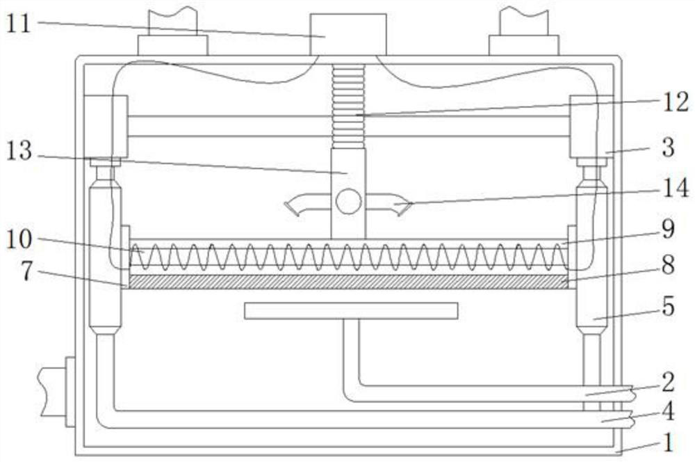
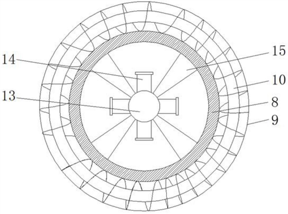
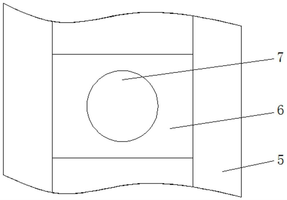
[0018] see Figure 1-3 , a settling tank for oil field sewage, comprising a tank body 1, a liquid inlet pipe 2, an oil sump 3, and a liquid delivery pipe 4, the tank body 1 is composed of a sludge area 16, a sewage area 17, an emulsification area 18, and a dirty oil area 19, The arrangement of the sludge area 16, sewage area 17, emulsification area 18, and dirty oil area 19 is affected by the density difference. The density of the dirty oil area 19 is the smal...


PUM


Abstract

The invention relates to the technical field of oilfield sewage treatment, and discloses a settling tank for oilfield sewage, which includes a tank body, a liquid inlet pipe, an oil collection tank, and a liquid infusion pipe. The sludge area is located at the bottom of the tank body, the sewage area is located above the sludge area, and the emulsification area is located above the sewage area. The settling tank for oil field sewage, through the density difference between the floating plate, sliding plate and the sewage area and the oily area, the floating plate is always floating in the middle of the sewage area and the oily area, thus driving the drug delivery pipe to be located in the emulsified layer , the sprayed demulsifier directly contacts the emulsification area, realizing the rapid demulsification of the emulsification area generated during the separation process of crude oil. On the one hand, a large amount of demulsifier is saved, so that the demulsifier directly acts on the emulsification area, and on the other hand, the elimination of emulsification is accelerated The formation of the zone reduces the loss of oil temperature during the separation process of crude oil, reduces the viscosity of crude oil, and thus speeds up the separation between crude oil and sewage.

Description

technical field [0001] The invention relates to the technical field of oilfield sewage treatment, in particular to a settling tank for oilfield sewage. Background technique [0002] Crude oil is a dark brown viscous oily liquid with green fluorescence and a special smell. It is a mixture of various liquid hydrocarbons such as alkanes, naphthenes, aromatic hydrocarbons and olefins. [0003] Before crude oil is exploited, the surface soil is usually destroyed by drilling rigs to form an oil well, and then the crude oil is pumped out from the surface with a pumping machine. During the pumping process, the sewage, oil-in-water, and water-in-oil contained in the crude oil , and impurities (paraffin, asphalt) are transported to the settling tank for filtration. The working principle of the existing settling tank can be referred to Figure 4 , the heated crude oil enters the tank body 1 from the liquid inlet pipe 2, and with the increase of the solution, coupled with the reason of...

Claims


Application Information

Patent Timeline
Patent Type & Authority Patents(China)
IPC IPC(8): C10G33/04C02F1/40
CPCC10G33/04C02F1/40
Inventor 赵万生赵明王成刘洋周敏杰张春波姜兴安
Owner 肇州县海崴井下作业有限公司
Why Eureka
Try Eureka