Projectile roll angle control method based on reaction flywheel

A technology of a reaction flywheel and a control method, applied in the field of navigation, can solve the problems of excessive weight of the projectile body and difficult control, and achieve the effect of a simple and feasible control method.

Active Publication Date: 2020-05-05
CHINA THREE GORGES UNIV
View PDF7 Cites 0 Cited by
  • Summary
  • Abstract
  • Description
  • Claims
  • Application Information

AI Technical Summary

Problems solved by technology

Excessive weight of the projectile will also bring certain difficulties to control

Method used


Image

  • Projectile roll angle control method based on reaction flywheel
  • Projectile roll angle control method based on reaction flywheel
  • Projectile roll angle control method based on reaction flywheel

Examples


Embodiment Construction

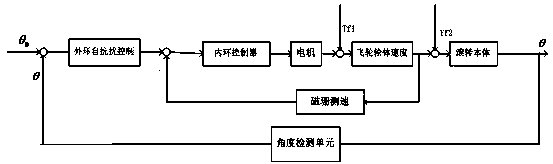
[0050] A method for controlling the roll angle of a projectile based on a reaction flywheel, including the following steps:

[0051] Step 1: Select a general-purpose servo motor as the driving motor of the reaction flywheel, and establish a dynamic model with the roll angle as the controlled variable and the speed of the reaction flywheel, that is, the speed of the servo motor as the control variable, as follows:

[0052]

[0053] Where:

[0054] J b ——Moment of inertia of the rolling body;

[0055] θ——rolling angle;

[0056] J w ——The moment of inertia of the reaction flywheel;

[0057] Ω——reaction flywheel angular velocity;

[0058] M d ——Interference torque;

[0059] Assume Available system expressions:

[0060]

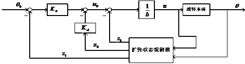
[0061] Let x 1 =y, x 3 =f The expression of the expanded state space of the system is as follows:

[0062]

[0063]

[0064] Step 2: Based on the dynamic model of the system established in Step 1, an expanded state observer is established to observe the roll angle, roll angula...


PUM


Abstract

The invention provides a projectile roll angle control method based on a reaction flywheel. The projectile roll angle control method comprises the following steps that step one, a dynamical model witha roll angle as the controlled quantity and the rotation speed of the reaction flywheel as the control quantity is established; step two, an expansion state observer based on the systemic dynamical model established in the step one is established to observe the roll angle, roll angle velocity and disturbance torque; step three, a PD controller based on the roll angle, the roll angle velocity andthe disturbance torque observed in the step two is designed, and is subjected to compensation for the disturbance torque; and step four, the extended state observer established in the step two and thecontroller established in the step three are subjected to certification for stability. According to the projectile roll angle control method, the dynamical model of a projectile roll channel is analyzed, then the corresponding expansion state observer is further designed to observe total disturbance in a flight process of a projectile, thus the compensation for the disturbance is further achieved, and stable control of the projectile roll channel is achieved through design of the controller.

Description

Technical field [0001] The invention relates to the technical field of navigation, in particular to a method for controlling the roll angle of a projectile based on a reaction flywheel. Background technique [0002] During the precise control of the projectile, the stability of the projectile’s rolling channel and the ability to quickly adjust the roll angle are the keys to achieving precise alignment of the projectile and stable flight control. During the flight of the projectile, it will be subjected to various disturbances such as disturbance torque generated by aerodynamic friction, disturbance between motor bearings and so on. The existence of these disturbing moments will reduce the accuracy of the projectile roll angle control. Excessive weight of the projectile will also bring certain difficulties to control. Summary of the invention [0003] The technical problem to be solved by the present invention is to provide a method for controlling the roll angle of the projectil...

Claims


Application Information

Patent Timeline
Patent Type & Authority Applications(China)
IPC IPC(8): F42B15/01
CPCF42B15/01
Inventor 吴正平邓聪颜华岑帅红
Owner CHINA THREE GORGES UNIV
Why Eureka
Try Eureka