A kind of PE pipe material and its processing system and processing method

A processing system and pipe technology, applied in the field of pipe processing, can solve the problems of uneven and rough cutting surface, affecting installation, economic loss, etc., and achieve the effect of scientific and reasonable processing method, convenient post-installation, efficient and stable cutting

Active Publication Date: 2020-09-11
浙江兆和管业有限公司
View PDF6 Cites 0 Cited by
  • Summary
  • Abstract
  • Description
  • Claims
  • Application Information

AI Technical Summary

Problems solved by technology

When the worker pulls the saw blade, due to the high friction between the saw blade and the cutting surface of the PE pipe, the labor intensity is high when the worker cuts, and the PE pipe moves during cutting, which not only increases the difficulty of sawing the pipe, but also the cutting surface is uneven and rough, which affects the later stage The installation reduces the qualified rate of PE pipes and causes economic losses

Method used


Image

  • A kind of PE pipe material and its processing system and processing method
  • A kind of PE pipe material and its processing system and processing method
  • A kind of PE pipe material and its processing system and processing method

Examples


Embodiment 1

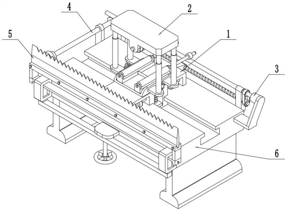
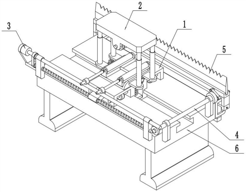
[0038] Such as Figure 1-11As shown, a PE pipe processing system includes a movable seat 1, a clamping device 2, a driving device 3, a linkage device 4, a pipe cutting device 5 and a processing frame 6, and the movable seat 1 is slidably connected to the processing frame 6 Above; the clamping device 2 is slidably connected to the movable seat 1; the driving device 3 is fixedly connected to the processing frame 6; the driving device 3 is transmission-connected to the movable seat 1, the clamping device 2 and the linkage device 4; The linkage device 4 is fixed on the processing frame 6 ; the linkage device 4 is connected to the pipe cutting device 5 through transmission; When the PE pipe processing system described above processes PE pipes, the PE pipes are installed on the clamping device 2; the position of the pipe cutting device 5 is adjusted to make it contact with the pipe surface of the PE pipes, and to generate upward pressure on the PE pipes. The pressure; connect the d...

Embodiment 2

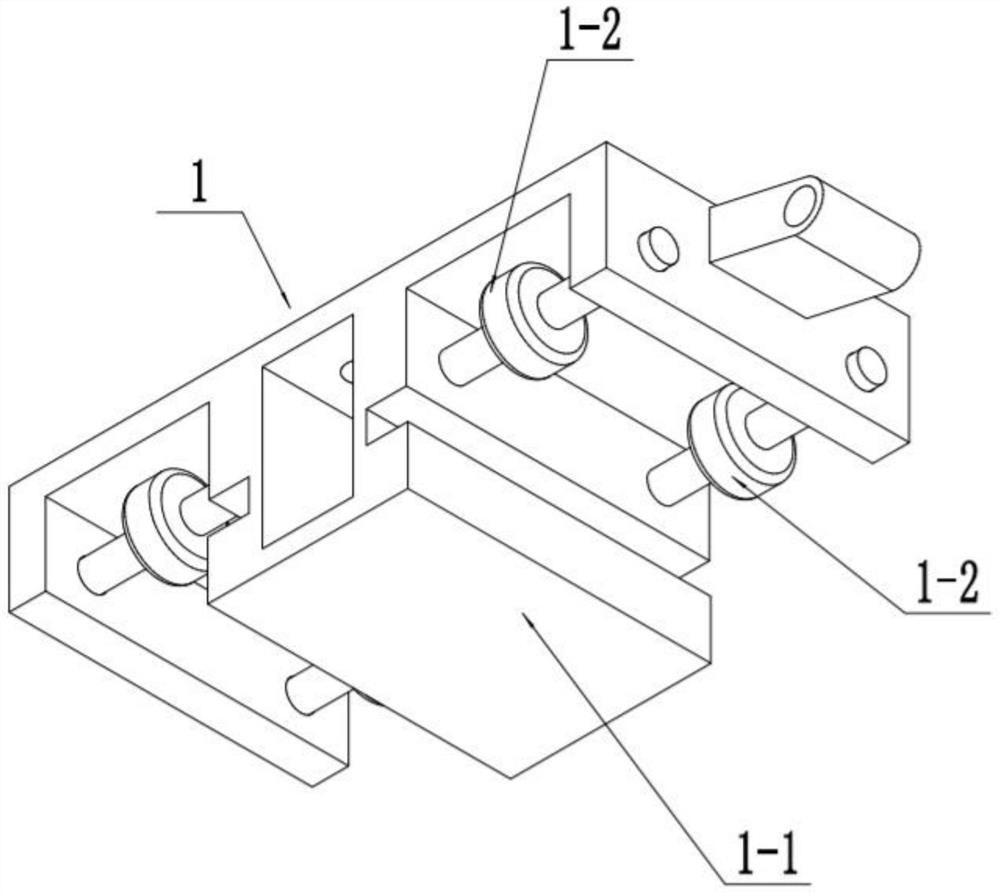
[0040] Such as Figure 1-11 As shown, the movable seat 1 includes a sliding seat body 1-1 and auxiliary wheels 1-2; the middle part of the lower end of the sliding seat body 1-1 is slidingly fitted in the T-shaped chute of the processing frame 6; the sliding The front and rear sides of the lower end of the seat body 1-1 are respectively rotated and connected to two auxiliary wheels 1-2; the wheel surfaces of the two auxiliary wheels 1-2 are rolled and fitted on the processing frame 6; the driving device 3 is connected by transmission and sliding Seat body 1-1. After the driving device 3 starts, it can drive the lower end of the sliding seat body 1-1 to slide in the T-shaped chute of the processing frame 6, and the auxiliary wheel 1-2 rolls on the top surface of the processing frame 6, driven by the sliding seat body 1-1. The clamping device 2 and the PE pipe on the clamping device 2 move horizontally.

Embodiment 3

[0042] Such as Figure 1-11 As shown, the clamping device 2 includes an upper seat 2-1, a lower seat 2-2, an electric push rod 2-3, an upper clamping tube 2-4, a lower clamping tube 2-5, a rotating shaft 2-6, a first worm gear 2-7, sliding frame 2-8, two-way screw rod 2-9, turntable 2-10, sliding column 2-11, compression spring 2-12 and horizontal plate 2-13; the lower end of the lower seat 2-2 is fixedly connected Two sliding columns 2-11, the two sliding columns 2-11 are slidingly fitted on the processing frame 6, the lower ends of the two sliding columns 2-11 are fixedly connected with a horizontal plate 2-13, and the horizontal plate 2-13 is slidingly fitted on the In the central groove of the processing frame 6; the sliding column 2-11 is covered with a compression spring 2-12, and the compression spring 2-12 is located between the horizontal plate 2-13 and the top surface of the central groove; the lower seat Two electric push rods 2-3 are respectively fixedly connected...


PUM


Abstract

The invention discloses a PE pipe and a machining system and method thereof. The PE pipe comprises a base layer pipe, a metal mesh layer and a wear-resistant rubber layer, wherein the base layer pipeis fixed on the inner side of the metal mesh layer; and the metal mesh layer is fixed on the inner side of the wear-resistant rubber layer. The method comprises the steps that 1, the PE pipe is mounted on a pipe clamping device; 2, the position of a pipe cutting device is adjusted to make the pipe cutting device in contact with the pipe surface of the PE pipe and generate upward pressure on the PEpipe; and 3, a driving device is connected with a power supply and started, and the driving device drives the pipe cutting device to be subjected to reciprocating cutting motion in the horizontal direction through a linkage device; the driving device controls the pipe clamping device to drive the PE pipe on the inner side of the pipe clamping device to rotate while driving the pipe clamping device to move in the horizontal direction, so that different positions of the pipe surface of the PE pipe are in contact with the pipe cutting device, and the PE pipe is cut by the pipe cutting device subjected to the reciprocating cutting motion in the horizontal direction; and after cutting is finished, the PE pipe is removed from the pipe clamping device, and the PE pipe with the required length isobtained.

Description

technical field [0001] The invention relates to the field of pipe processing, in particular to a PE pipe, a processing system and a processing method thereof. Background technique [0002] PE is polyethylene plastic, the most basic kind of plastic, plastic bags, plastic wrap, etc. are PE, HDPE is a high crystallinity, non-polar thermoplastic resin. PE pipes include medium-density polyethylene pipes and high-density polyethylene pipes. It is suitable for conveying gaseous artificial gas, natural gas, and liquefied petroleum gas. Compared with steel pipes, the construction process is simple and has certain flexibility. What's more, it is not used for anti-corrosion treatment, which will save a lot of procedures. [0003] Since PE pipes are produced continuously, in order to facilitate the storage and transportation of the produced PE pipes, it is necessary to cut the continuously produced PE pipes. The traditional cutting method adopts manual cutting, and the cutting is perf...

Claims


Application Information

Patent Timeline
Patent Type & Authority Patents(China)
IPC IPC(8): B26D1/10B26D3/16B26D7/02F16L9/147F16L57/06
CPCB26D1/10B26D3/16B26D7/02B26D2007/013F16L9/147F16L57/06
Inventor 史春龙
Owner 浙江兆和管业有限公司
Why Eureka
Try Eureka