
Atomic spin multi-channel detection method and device based on spatial light modulator

A spatial light modulator and multi-channel detection technology, applied in the direction of measuring devices, instruments, scientific instruments, etc., can solve the problems of lack of modulation, fixed demodulation frequency, complex mechanical structure and other problems of differential polarization method, and achieve strong design and operation Simple, Small Effects

Active Publication Date: 2020-04-28
BEIHANG UNIV
View PDF3 Cites 7 Cited by
  • Summary
  • Abstract
  • Description
  • Claims
  • Application Information

AI Technical Summary

Problems solved by technology

For multi-channel atomic spin detection, the differential polarization method lacks modulation, and the low-frequency response of the signal is poor, so it is impossible to acquire multi-channel signals at the same time; the Faraday modulation method uses a coil to generate a variable magnetic field for modulation, and complex environmental conditions require magnetic shielding and temperature control. It is impossible to demodulate multi-channel signals at the same time; the photoelastic modulator requires a complex control mechanism and a fixed demodulation frequency, so it cannot demodulate multi-channel signals at the same time
At present, the above three methods are used for multi-channel atomic spin detection. Using one detection and demodulation device cannot guarantee the simultaneity of multi-channel signals. Using multiple detection and demodulation devices not only requires the same number of devices and multi-channels, but also the subsequent signal The increase in the number of corresponding devices such as data processing equipment lock-in amplifiers increases the complexity of the overall device, reduces the overall engineering applicability, and is not conducive to the integration and miniaturization of the device
At present, the existing atomic spin precession detection method is difficult to achieve industrial integration at the same time, and multi-channel signals can be obtained without delay demodulation

Method used


Image

  • Atomic spin multi-channel detection method and device based on spatial light modulator
  • Atomic spin multi-channel detection method and device based on spatial light modulator
  • Atomic spin multi-channel detection method and device based on spatial light modulator

Examples


Embodiment Construction

[0021] Below with the accompanying drawings ( Figure 1-Figure 2 ) to illustrate the present invention.

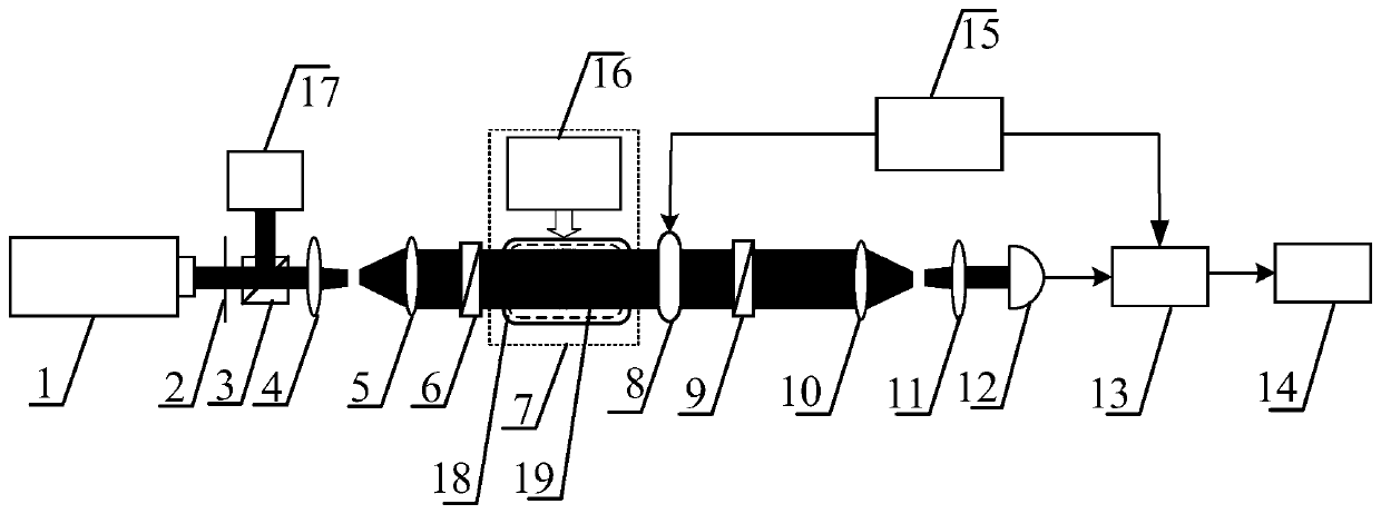
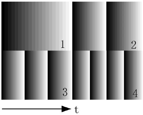
[0022] figure 1 It is a structural schematic diagram of an atomic spin multi-channel detection device based on a spatial light modulator for implementing the present invention. figure 2 It is a schematic diagram of the four-channel grayscale modulation of the spatial light modulator over time. refer to Figure 1 to Figure 2As shown, a method for multi-channel detection of atomic spin based on a spatial light modulator comprises the following steps: a spatial light modulator 8 is set between the atomic sensing module 7 and the second Glan-Taylor prism 9, and the spatial light modulator The modulator 8 performs multi-channel modulation on the light beam carrying the optical rotation angle information from the atomic sensing module 7, so as to obtain the detection result of the multi-channel atomic spin precession signal. The spatial light modulator 8 is driven by the gr...


PUM


Abstract

The invention discloses an atomic spin multi-channel detection method and device based on a spatial light modulator. The method and the device are realized by arranging a spatial light modulator between an atom sensing module and a second Glan-Taylor prism. The spatial light modulator is used for carrying out multi-channel modulation on optical rotation angle information carried by the atom sensing module to obtain a detection result of a multi-channel atomic spin precession signal. A new thought is provided for development of a novel miniaturized and integrated ultrahigh-sensitivity inertia and magnetic field measuring device. The method and the device can be used for geological exploration, biomedical imaging and basic physical research.

Description

technical field [0001] The invention relates to quantum sensing instrument measurement technology, in particular to a method and device for multi-channel detection of atomic spin based on a spatial light modulator, by setting a spatial light modulator between the atomic sensing module and the second Glan-Taylor prism Realize that the spatial light modulator performs multi-channel modulation on the optical rotation angle information carried by the atomic sensing module to obtain the detection results of the multi-channel atomic spin precession signal, which is useful for the development of new ultra-high sensitivity inertial and magnetic field measurements The miniaturization and integration of devices provides new ideas, which can serve geological exploration, biomedical imaging, and basic physics research. Background technique [0002] With the vigorous development of quantum mechanics and quantum optics and the rapid development of atomic manipulation technology, in recent...

Claims


Application Information

Patent Timeline
Patent Type & Authority Applications(China)
IPC IPC(8): G01N21/84G01N21/01
CPCG01N21/01G01N21/84
Inventor 房建成房秀杰翟跃阳魏凯赵天马丹跃邢博铮肖志松
Owner BEIHANG UNIV
Learn More