


Quick Research
Generate reliable direction feasibility study reports for your R&D in just a few steps.

Technical Q&A
Discover and master advanced knowledge NOW. Basics, ideas, possibilities, all at once.

Find Solutions
As an expert in R&D theories, this can generate solutions to your technical problems instantly.

Evaluate Feasibility
Analyze your overall solution with one click, know your potential R&D risks in advance.

Monitor Landscape
Get weekly tech updates, stay abreast of the latest tech innovations and key insights.
A power generation device coupled with biomass gasification and oxyfuel combustion combined cycle
Oxygen-enriched combustion and combined cycle technology, applied in biofuels, gas turbine installations, gasification processes, etc., can solve problems such as low power generation efficiency, low biomass gasification efficiency, and difficulty in CO2 separation in power generation systems.
- Summary
- Abstract
- Description
- Claims
- Application Information
AI Technical Summary
Problems solved by technology
Method used
Image

Examples
Embodiment 1
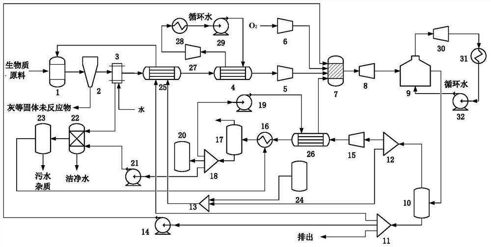
[0042] A power generation device coupled with biomass gasification and oxyfuel combustion combined cycle, the structure diagram of the device is shown in figure 1 As shown, the specific working process is as follows:
[0043] (1) Biomass gasification
[0044] The biomass raw material is added to the gasifier 1, from CO 2 Part of CO separated by splitter A 12 2 , part of the water separated by the water separator 11 and O 2 O in tank 24 2 As a gasification agent, from CO 2 Part of CO separated by splitter A 12 2 and O 2 O in tank 24 2 After mixing, part of the water separated by the water separator 11 is preheated by the preheater 25 and enters the gasification furnace 1 to gasify the biomass raw material. The gasification pressure is 1 atmospheric pressure and the gasification temperature is 600~ 1000°C. The crude synthesis gas produced by gasification enters the cyclone separator 2 to remove unreacted solid impurities, and then enters the water scrubber 3 to wash off...
Embodiment 2
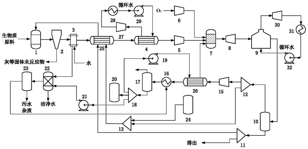
[0052] A power generation device coupled with biomass gasification and oxyfuel combustion combined cycle, its structure schematic diagram is as follows figure 2 shown. This embodiment is different from Embodiment 1 in that the water discharged from the bottom of the gas-water separator 10 is separated into two parts by the water separator 11, one part is directly discharged, and the other part is used as a gasification agent, which is preheated by the preheater 25. After heating, it enters the gasifier 1 to participate in gasification. Therefore, in this embodiment, at the combustion temperature of oxyfuel combustion, the neutralizing medium is only the CO separated from the flue gas 2 .
Embodiment 3
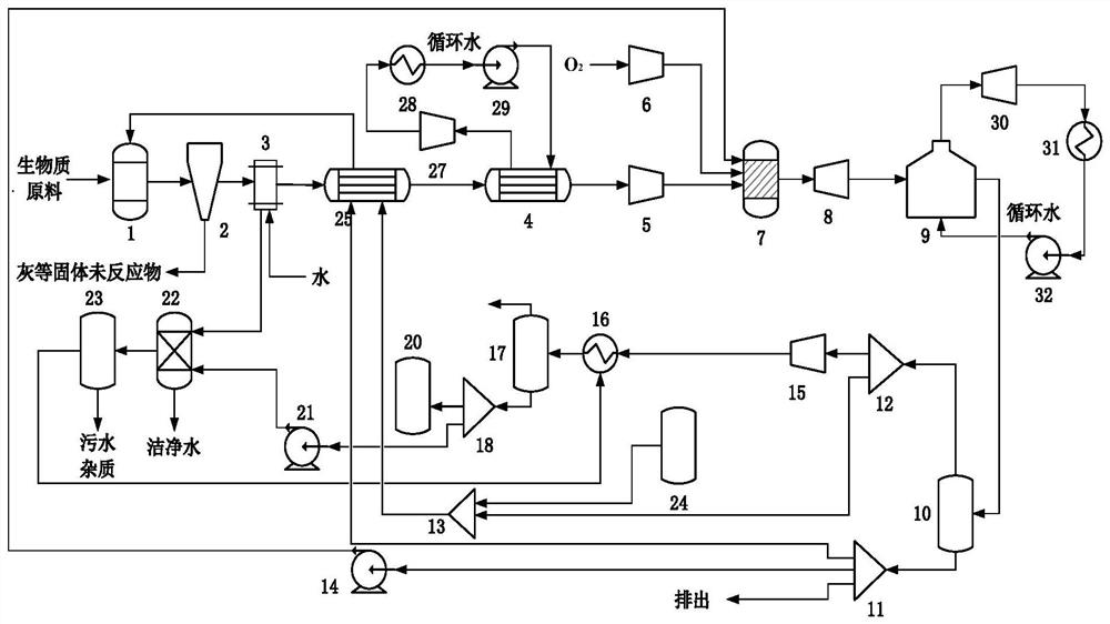
[0054] A power generation device coupled with biomass gasification and oxyfuel combustion combined cycle, its structure schematic diagram is as follows image 3 shown. This embodiment is different from embodiment 1 in that, with CO 2 After the main flue gas is compressed to 0.6MPa by the flue gas compressor 15, it directly enters the CO 2 In the condenser 16, the CO in the flue gas 2 is condensed into a liquid state, discharged from the bottom of the gas-liquid separator 17 and stored in CO 2 In the storage tank 20 , other non-condensable gases are discharged from the top of the gas-liquid separator 17 . Therefore, in this embodiment, the neutralizing medium at the combustion temperature of oxy-fuel combustion is only circulating water.
PUM
 Abstract
Description
Claims
Application Information
 - R&D Engineer
- R&D Manager
- IP Professional
- Industry Leading Data Capabilities
- Powerful AI technology
- Patent DNA Extraction
Browse by: Latest US Patents, China's latest patents, Technical Efficacy Thesaurus, Application Domain, Technology Topic, Popular Technical Reports.
© 2024 PatSnap. All rights reserved.Legal|Privacy policy|Modern Slavery Act Transparency Statement|Sitemap|About US| Contact US: help@patsnap.com