
In-situ leaching uranium mining full-process circulation experimental device

An experimental device and in-situ leaching uranium mining technology are applied in the field of in-situ leaching and mining uranium full-process cycle experimental devices, which can solve the problems of long time, large leaching liquid-solid ratio, only tens of milliliters to hundreds of milliliters, etc., and achieves convenient operation. Effect

Inactive Publication Date: 2020-04-28
BEIJING RESEARCH INSTITUTE OF CHEMICAL ENGINEERING AND METALLURGY
View PDF6 Cites 2 Cited by
  • Summary
  • Abstract
  • Description
  • Claims
  • Application Information

AI Technical Summary

Problems solved by technology

[0002] The existing in-situ leaching uranium column leaching experiment device can only complete the leaching experiment, without resin adsorption experiment, and the leaching solution cannot be recycled. As a result, the process of in-situ leaching and mining of uranium cannot be truly simulated.
Usually there is no accumulation of impurity ions during acid column leaching, and the results of indoor experiments are better than those of field experiments; CO 2 +O 2 HCO of complexed uranium in leaching solution during column leaching 3 - Ions cannot be accumulated, and the results of indoor experiments are worse than field experiments, resulting in CO 2 +O 2 The column leaching experiment has a large liquid-solid ratio and a long time
[0003] Due to the small flow rate of the laboratory column leaching experiment, the cumulative flow rate per day is usually only tens of milliliters to hundreds of milliliters. In order to realize the full-process recycling and precise control of the leachate, the existing equipment cannot control and measure the leachate flow. Require

Method used


Image

  • In-situ leaching uranium mining full-process circulation experimental device

Examples


Embodiment Construction

[0022] The present invention will be described in detail below in conjunction with the accompanying drawings and specific embodiments.

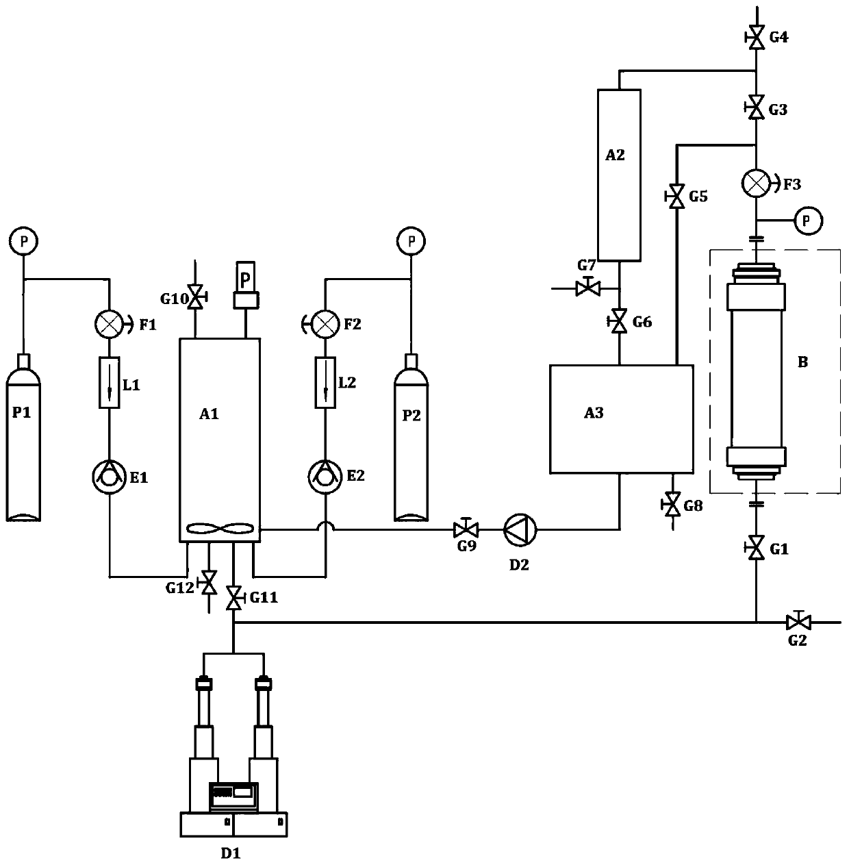
[0023] Such as figure 1 As shown, the composition and connection relationship of the in-situ leaching uranium full-process circulation experimental device of the present invention are as follows: the constant-speed constant-pressure double-cylinder pump D1 is connected to the high-pressure test column B through the leaching agent inlet valve G1, and the high-pressure test column B The outlet is equipped with a column leaching outlet pressure regulating valve F3, and the column leaching outlet pressure regulating valve F3 is connected to the upper part of the ion exchange column A2 after passing through the leaching liquid outlet valve G3, and the lower part of the ion exchange column A2 is connected to the liquid collection tank A3 through the adsorption tail liquid valve G6, The liquid collecting tank A3 is connected to the stirring tank A1 ...


PUM


Abstract

The invention belongs to the technical field of in-situ leaching uranium mining experimental equipment, and particularly relates to an in-situ leaching uranium mining full-process circulation experimental device. A constant-speed constant-pressure double-cylinder pump is connected with a high-pressure test column through a leaching agent liquid inlet valve, wherein a column leaching port pressureregulating valve is arranged at an outlet of the high-pressure test column; the column leaching port pressure regulating valve is connected with the upper part of an ion exchange column after passingthrough a leaching agent liquid outlet valve; the lower part of the ion exchange column is connected into a liquid collecting tank through an adsorption tail liquid valve; the liquid collecting tank is connected to a stirring tank through a reciprocating plunger pump and a liquid collecting valve; an oxygen steel cylinder is connected to the stirring tank through an oxygen pressure regulating valve, an oxygen flow controller and an oxygen one-way valve; a carbon dioxide steel cylinder is connected to the stirring tank through a carbon dioxide pressure regulating valve, a carbon dioxide flow controller and a carbon dioxide one-way valve; the stirring tank is connected to the constant-speed constant-pressure double-cylinder pump through a liquid distribution valve; and the column leaching port pressure regulating valve is connected to the liquid collecting tank through a leaching liquid non-adsorption valve. The whole equipment process is a process circulation process, only transparent pipelines need to be checked and replaced at regular intervals, and operation is convenient.

Description

technical field [0001] The invention belongs to the technical field of experimental equipment for uranium mining by in-situ leaching, and in particular relates to a full-process circulation experimental device for uranium mining by in-situ leaching. Background technique [0002] The existing in-situ leaching uranium column leaching experiment device can only complete the leaching experiment without resin adsorption experiment, and the leaching solution cannot be recycled. As a result, the process of in-situ uranium extraction cannot be truly simulated. Usually there is no accumulation of impurity ions during acid column leaching, and the results of indoor experiments are better than those of field experiments; CO 2 +O 2 HCO of complexed uranium in leaching solution during column leaching 3 - Ions cannot be accumulated, and the results of indoor experiments are worse than field experiments, resulting in CO 2 +O 2 In column leaching experiment, the leaching liquid-solid r...

Claims


Application Information

Patent Timeline
IPC IPC(8): C22B60/02C22B3/02C22B3/24C22B3/06
CPCC22B3/02C22B3/06C22B3/24C22B60/0226C22B60/0265
Inventor 江国平霍建党张建华闻振乾王亮原渊
Owner BEIJING RESEARCH INSTITUTE OF CHEMICAL ENGINEERING AND METALLURGY
Learn More