
Medical accelerator, dose monitoring system, and dose monitoring method of medical accelerator

An accelerator and dose technology, applied in dosimeter, radiotherapy, X-ray/γ-ray/particle irradiation therapy, etc., can solve the problems of inapplicability, achieve convenient operation, improve convenience and accuracy, and novel methods

Pending Publication Date: 2020-04-28
TSINGHUA INNOVATION CENT IN DONGGUAN +1
View PDF0 Cites 1 Cited by
  • Summary
  • Abstract
  • Description
  • Claims
  • Application Information

AI Technical Summary

Problems solved by technology

[0003] The medical accelerator of the present invention directly utilizes electron beams to treat tumors, and the electron beams are transmitted in a thin tube (inner diameter less than 5 mm) from the acceleration tube to the tumor, and cannot directly pass through the ionization chamber, so the ionization chamber is not suitable for this kind of equipment At present, there is no relevant dose monitoring method at home and abroad to test the therapeutic dose of such Ono's electron beam online

Method used


Image

  • Medical accelerator, dose monitoring system, and dose monitoring method of medical accelerator
  • Medical accelerator, dose monitoring system, and dose monitoring method of medical accelerator
  • Medical accelerator, dose monitoring system, and dose monitoring method of medical accelerator

Examples


Embodiment 1

[0078] Before treatment, operate according to the above steps P1-P4, the resistance value of the resistor is 50Ω, and the test data obtained are shown in Table 1.

[0079] Table 1 The test result table of U and H before treatment

[0080]

[0081] By processing the test results of U and H, K=1.597 is obtained.

Embodiment 2

[0083] During the treatment process, dose monitoring is carried out according to steps S1-S3, and the test value of voltage U and the calculated value of dose rate H of the second electron beam are shown in Table 2.

[0084] Table 2 The test result table of U and H in the course of treatment

[0085]

[0086]

[0087] In this embodiment, the dose rate of the second electron beam (used for treatment) is calculated by monitoring the voltage of the first electron beam, and the dose rate monitoring is carried out without affecting the treatment.

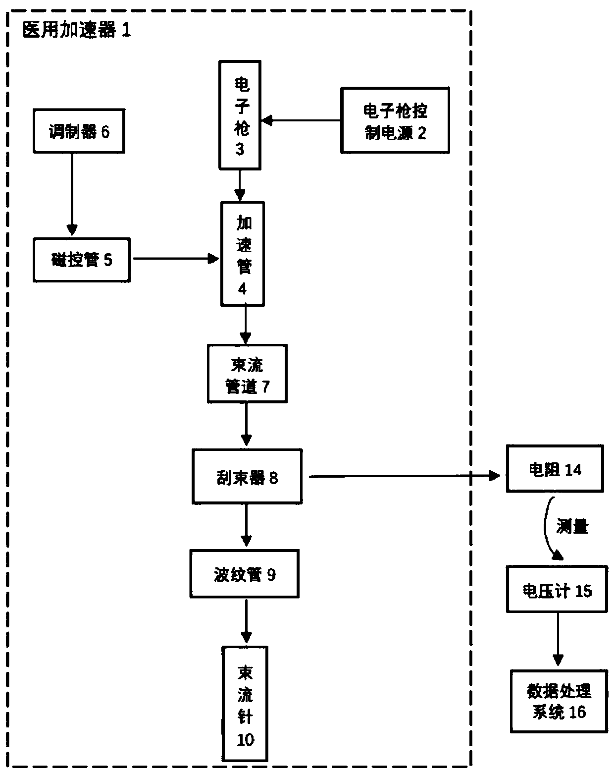
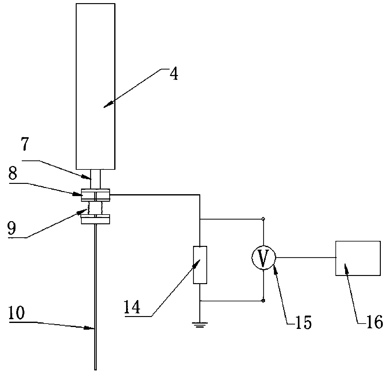
[0088] The invention uses the first electron beam to move directionally between the beam scraper and the wire to generate a current, and synchronously tests the voltage at both ends of the resistor, and obtains the dose rate of the electron beam through the test voltage value, which does not affect the treatment process and can realize on-line monitoring of the first The dose of two electron beams improves the convenience and accur...


PUM

PropertyMeasurementUnit
Resistanceaaaaaaaaaa

Abstract

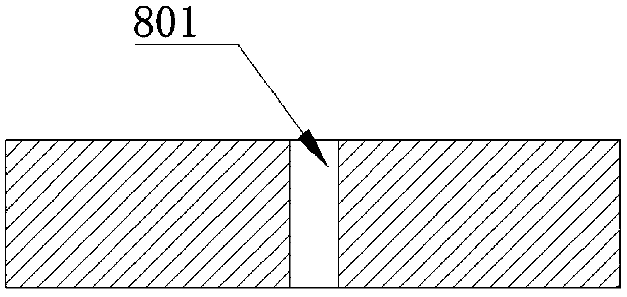
The invention relates to the technical field of medical accelerators, and discloses a medical accelerator. The medical accelerator includes an acceleration pipe, a beam pipeline, a beam scraper, a corrugated pipe and a beam needle, and the beam pipeline, the beam scraper, the corrugated pipe and the beam needle are connected in sequence and share a central axis and communicate to form a straight channel for transmission of an electron beam in the straight channel; and an inner pore diameter of the beam scraper is smaller than an inner pore diameter of the beam channel. The invention also discloses a dose monitoring system. The dose monitoring system includes a resistance, a voltmeter, a conductor and a data processing system, the beam scraper, the resistance and the ground are sequentiallyconnected through the conductor, and the voltmeter is used to test a voltage value at both ends of the resistance; and the data processing system processes the voltage value to obtain a dose of the electron beam. The invention also discloses a dose monitoring method. A current is generated through part of the electron beam, the voltage at both ends of the resistance is simultaneously tested, andthe dose rate of the electron beam is obtained by testing the voltage value, so that the treatment process is not affected, and online monitoring of the dose of the electron beam can be realized.

Description

technical field [0001] The invention relates to the technical field of medical accelerators, in particular to a medical accelerator, a dose monitoring system and a dose monitoring method. Background technique [0002] According to the requirements in the national standard GB9706.5-2008, the dose monitoring system must be included in the medical electron linear accelerator. The dose monitoring system used in traditional medical accelerators consists of ionization chamber detectors and their auxiliary circuits. The ionization chamber is located in the radiation system, installed between the uniform filter or the scattering foil and the secondary collimator of the photon line, and is composed of several pole pieces, two of which are used to monitor the radiation field. For the uniformity of the direction, one is used to monitor the energy change of the radiation, and two are used to detect the absorbed dose of the radiation. Most of the dose monitoring systems of traditional ...

Claims


Application Information

Patent Timeline
IPC IPC(8): A61N5/10G01T1/02
CPCA61N5/1071G01T1/02
Inventor 王平蒋晓鹏刘朝生
Owner TSINGHUA INNOVATION CENT IN DONGGUAN
Learn More