rotary compressor
A technology of rotary compressors and compression chambers, which is applied in the direction of rotary piston machines, rotary piston pumps, rotary piston/swing piston pump components, etc. It can solve the problems that the piston cannot be installed on the eccentric part, etc., and achieve suppression Reliability drop, effect of suppressing drop in load capacity
- Summary
- Abstract
- Description
- Claims
- Application Information
AI Technical Summary
Problems solved by technology
Method used
Image
Examples
no. 1 approach 》
[0070] A first embodiment of the present invention will be described.
[0071] - The overall structure of the compressor -
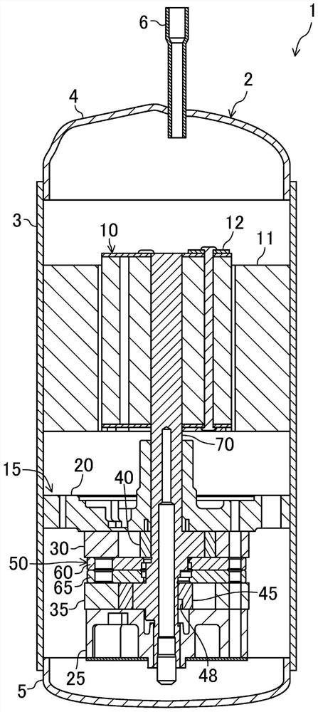
[0072] like figure 1 As shown, the compressor of the present embodiment is a hermetic rotary compressor 1 . In the rotary compressor 1 , the compression mechanism 15 and the electric motor 10 are accommodated in the casing 2 . The rotary compressor 1 is installed in a refrigerant circuit that performs a vapor compression refrigeration cycle, and compresses the refrigerant after sucking in the refrigerant evaporated by the evaporator.
[0073] The casing 2 is a cylindrical airtight container in an upright state. The casing 2 includes a cylindrical trunk portion 3 and a pair of end plates 4 and 5 that block the ends of the trunk portion 3 . A suction pipe (not shown) is attached to the lower part of the trunk portion 3 . A discharge pipe 6 is attached to the upper end plate 4 .
[0074] The electric motor 10 is arranged in the upper part of the inner...
no. 1 approach
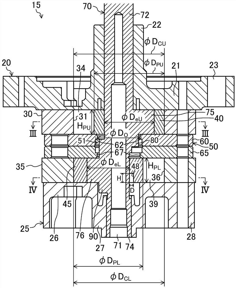
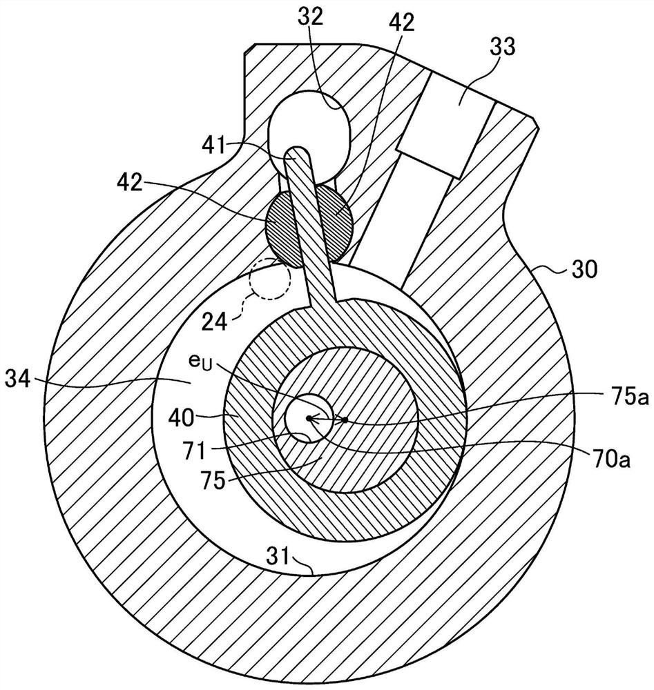
[0196] In addition, in the first embodiment, the drive shaft 70 is configured such that the distance r, which is the minimum value of the distances from the rotation center axis 70 a of the drive shaft 70 to the outer peripheral surface of the upper eccentric portion 75 , 8 Radius R at the main shaft portion 72 M above (r 8 =R eU -e U ≥R M ). That is, the drive shaft 70 is configured such that the outer surface of the drive shaft 70 is not recessed toward the eccentric side at the upper eccentric portion 75 . Therefore, when the lower piston 45 and the upper piston 40 are assembled to the lower eccentric portion 76 and the upper eccentric portion 75 , the drive shaft 70 can be inserted into the lower piston 45 from the counter shaft portion 74 side, and can be inserted from the main shaft portion 72 side from the main shaft portion 72 side. The upper piston 40 is inserted for assembly. Accordingly, instead of assembling the upper piston 40 to the upper eccentric portion ...
other Embodiment approach
[0198] The above-mentioned embodiment may adopt the following structures.
[0199] In the above-described first embodiment, the first connection portion is formed between the secondary shaft portion 74 and the lower eccentric portion 76 so that the drive shaft 70 satisfies R eL -e L S , however, the first connection portion according to the present invention may be formed between the main shaft portion 72 and the upper eccentric portion 75 so that the drive shaft 70 satisfies R eU -e U M .
[0200] Specifically, in the above-described first embodiment, the lower cylinder 35 constitutes the first cylinder, the lower piston 45 constitutes the first piston, the lower eccentric portion 76 constitutes the first eccentric portion, and the counter shaft portion 74 constitutes the first eccentric portion. For the shaft portion, the upper cylinder 30 constitutes the second cylinder, the upper piston 40 constitutes the second piston, the upper eccentric portion 75 constitutes the sec...
PUM
 Abstract
Description
Claims
Application Information
 - R&D
- Intellectual Property
- Life Sciences
- Materials
- Tech Scout
- Unparalleled Data Quality
- Higher Quality Content
- 60% Fewer Hallucinations
Browse by: Latest US Patents, China's latest patents, Technical Efficacy Thesaurus, Application Domain, Technology Topic, Popular Technical Reports.
© 2025 PatSnap. All rights reserved.Legal|Privacy policy|Modern Slavery Act Transparency Statement|Sitemap|About US| Contact US: help@patsnap.com


