
Pixel circuit and driving method

A technology for pixel circuits and driving transistors, applied in instruments, static indicators, etc., can solve the problems of Vth drift, forward drift, and current drop of driving thin film transistors, and achieve the effect of suppressing further drift and ensuring stability.

Active Publication Date: 2020-04-17
SHENZHEN CHINA STAR OPTOELECTRONICS SEMICON DISPLAY TECH CO LTD
View PDF18 Cites 6 Cited by
  • Summary
  • Abstract
  • Description
  • Claims
  • Application Information

AI Technical Summary

Problems solved by technology

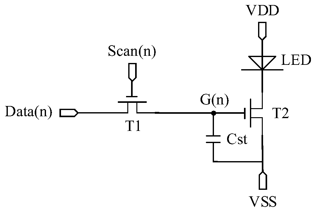
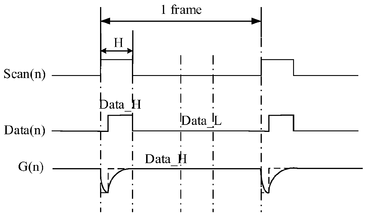
[0005] for Figure 1A In the middle driving thin film transistor T2, its gate voltage will be subjected to Data_H forward bias stress (PBTS) for a long time, and the subthreshold swing (Vth) of the driving thin film transistor T2 will drift forward, resulting in the current flowing through the driving thin film transistor T2 Decrease, which promotes the reduction of the brightness of the light-emitting device Mini-LED
In order to ensure the stability of brightness, Mini-LED must solve the problem of Vth drift caused by the forward bias of the driving thin film transistor T2

Method used


Image

  • Pixel circuit and driving method
  • Pixel circuit and driving method
  • Pixel circuit and driving method

Examples


Embodiment Construction

[0042] The technical solutions in the embodiments of the present application will be clearly and completely described below in conjunction with the drawings in the embodiments of the present application. Apparently, the described embodiments are only some of the embodiments of this application, not all of them. Based on the embodiments in this application, all other embodiments obtained by those skilled in the art without making creative efforts belong to the scope of protection of this application.

[0043]In the description of the present application, it should be understood that the terms "center", "longitudinal", "transverse", "length", "width", "thickness", "upper", "lower", "front", " Orientation indicated by rear, left, right, vertical, horizontal, top, bottom, inside, outside, clockwise, counterclockwise, etc. The positional relationship is based on the orientation or positional relationship shown in the drawings, which is only for the convenience of describing the ap...


PUM


Abstract

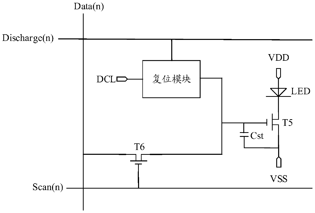
The invention discloses a pixel circuit and a driving method. The pixel circuit comprises a switching transistor, a driving transistor, a storage capacitor, a light emitting device and a reset module;the switching transistor is used for writing a data signal into a grid electrode of the driving transistor in data signal writing and light emitting stages, and the driving transistor drives the light emitting device to emit light according to the data signal; the reset module is used for outputting a reset signal to the grid electrode of the driving transistor according to the reset control signal in the reset signal writing and reset stage so as to neutralize the bias stress borne by the driving transistor in the data signal writing and light emitting stage, restrain further drifting of thethreshold voltage and guarantee the stability of the light-emitting brightness of the light emitting device.

Description

technical field [0001] The invention relates to the field of display technology, in particular to a pixel circuit and a driving method. Background technique [0002] The research on the sub-millimeter light-emitting diode (Mini Light-Emitting Diode, Mini-LED) as the backlight source of the display device is in the ascendant, and its display effect is comparable to that of the organic light-emitting diode (Organic Light-Emitting Diode, OLED), and it has a huge cost Advantage. [0003] Such as Figure 1A As shown, it is a circuit diagram of a traditional Mini-LED pixel circuit, Figure 1A The pixel circuit shown is composed of a switching thin film transistor T1, a driving thin film transistor T2 and a storage capacitor Cst. The gate of the switching thin film transistor T1 is connected to the scanning line, the first pole of the switching thin film transistor T1 is connected to the data line, and the second electrode of the switching thin film transistor T1 is connected to th...

Claims


Application Information

Patent Timeline
IPC IPC(8): G09G3/32G09G3/3225
CPCG09G3/32G09G3/3225G09G3/3258G09G2230/00G09G3/3426G09G2310/0251G09G2300/0819G09G2300/0842G09G2320/045
Inventor 石龙强
Owner SHENZHEN CHINA STAR OPTOELECTRONICS SEMICON DISPLAY TECH CO LTD
Learn More