
Dust removal and denitration integrated apparatus for high-temperature flue gas of cement kiln

A high-temperature flue gas and cement kiln technology, which is applied in the field of flue gas treatment, can solve the problems of uneven gas flow velocity in the catalyst layer, low or high flow velocity in the catalyst layer, uneven velocity distribution, etc., and achieve high dust removal and denitrification efficiency. The effect of a wide range of environments and simple equipment

Pending Publication Date: 2020-04-17
JIANGSU CTIEC ENVIRONMENTAL PROTECTION RES INST
View PDF0 Cites 2 Cited by
  • Summary
  • Abstract
  • Description
  • Claims
  • Application Information

AI Technical Summary

Problems solved by technology

[0003] SCR denitrification technology is used in cement kiln furnaces where particulate matter in the tail gas will block the catalyst. High-efficiency catalysts must be installed, and alkaline substances CaO and SO in the flue gas must be installed. 2 It will poison the catalyst. If the SCR is installed downstream of the dust collector, a flue gas reheater must be installed to heat the flue gas to the optimum working temperature of the catalyst. The unsatisfactory distribution of the SCR denitrification flow field will cause uneven mixing of ammonia nitrogen and smoke Severe dust accumulation in the channel and uneven flue gas flow velocity in the catalyst layer lead to problems such as low or high flow velocity in the local area of ​​the catalyst layer, excessive flow velocity deviation angle, etc., resulting in catalyst blockage or wear, and catalyst blockage and wear aggravate the uneven velocity distribution. Uniformity, forming a vicious circle, in view of this, it is necessary to study a cement kiln high-temperature flue gas dust removal and denitrification integrated device 4

Method used


Image

  • Dust removal and denitration integrated apparatus for high-temperature flue gas of cement kiln

Examples


Embodiment Construction

[0018] The present invention will be specifically introduced below in conjunction with the accompanying drawings and specific embodiments.

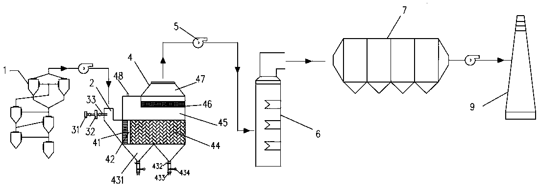
[0019] see figure 1 , a cement kiln high-temperature flue gas dust removal and denitrification integrated device 4 of the present invention, including a preheater 1, a dust removal and denitrification integrated device 4, a waste heat boiler 6, and a dust collector at the end of the pit, which are sequentially connected through pipelines according to the flue gas flow direction 7 and the chimney 9. An induced draft fan 5 is installed between the preheater 1 and the integrated dust removal and denitrification device 4 , between the integrated dust removal and denitrification device 4 and the waste heat boiler 6 , and between the dust collector 7 at the end of the pit and the chimney 9 .

[0020] The left end and the top of the dust removal and denitrification integrated device 4 are respectively provided with an air inlet and an air outle...


PUM

PropertyMeasurementUnit
thicknessaaaaaaaaaa

Abstract

The invention discloses a dust removal and denitration integrated apparatus for high-temperature flue gas of a cement kiln. The apparatus comprises a preheater, a dust removal and denitration integrated device, a waste heat boiler, a cellar tail dust remover and a chimney which are sequentially connected through pipelines in the flue gas flowing direction, a gas inlet and a gas outlet are respectively arranged at the left end and the top end of the dust removal and denitration integrated device, the gar inlet and the gas outlet are respectively connected with an inlet smoke box and a dust removal box, an outlet smoke box is arranged at the top of the dust removal box, an SCR denitration catalyst box is arranged between the dust removal box and the outlet smoke box, and a uniform distribution plate, a flow guide plate and a metal film dust removal mechanism are sequentially arranged in the dust removal and denitration integrated device from left to right. The apparatus is high in dust removal and denitration efficiency, resistant to chemical corrosion and long in service life.

Description

technical field [0001] The invention belongs to the technical field of flue gas treatment, and in particular relates to an integrated device for dust removal and denitrification of high-temperature flue gas from a cement kiln. Background technique [0002] As a big cement producing country, my country currently has more than 3,000 cement enterprises and about 1,800 new dry-process clinker production lines, covering 31 provinces and cities across the country. The annual emission of nitrogen oxides in the cement production process is about 2 million tons, accounting for about About 15% of the emissions of nitrogen oxides in the cement industry, the high emissions of nitrogen oxides in the cement industry have attracted the attention of the country, GB4915-2013 "Emission Standards for Air Pollutants in the Cement Industry" stipulates that since July 2015, nitrogen oxides in cement enterprises 400mg / m from March 1, 2014 (starting from March 1, 2014) 3 Emission standard, 320mg / m2 ...

Claims


Application Information

Patent Timeline
Patent Type & Authority Applications(China)
IPC IPC(8): B01D53/86B01D53/56B01D50/00F27D17/00
CPCB01D53/86B01D53/56F27D17/004B01D2258/0283B01D50/20Y02P10/25
Inventor 张志刚何义斌王东歌王彬郑美玲
Owner JIANGSU CTIEC ENVIRONMENTAL PROTECTION RES INST
Learn More