
Double-evaporator loop heat pipe

A loop heat pipe, double evaporator technology, applied in indirect heat exchangers, lighting and heating equipment, cooling/ventilation/heating renovation, etc. Reduce system mass and enhance the effect of thermo-hydraulic connection

Inactive Publication Date: 2020-04-14
HUAZHONG UNIV OF SCI & TECH
View PDF6 Cites 4 Cited by
  • Summary
  • Abstract
  • Description
  • Claims
  • Application Information

AI Technical Summary

Problems solved by technology

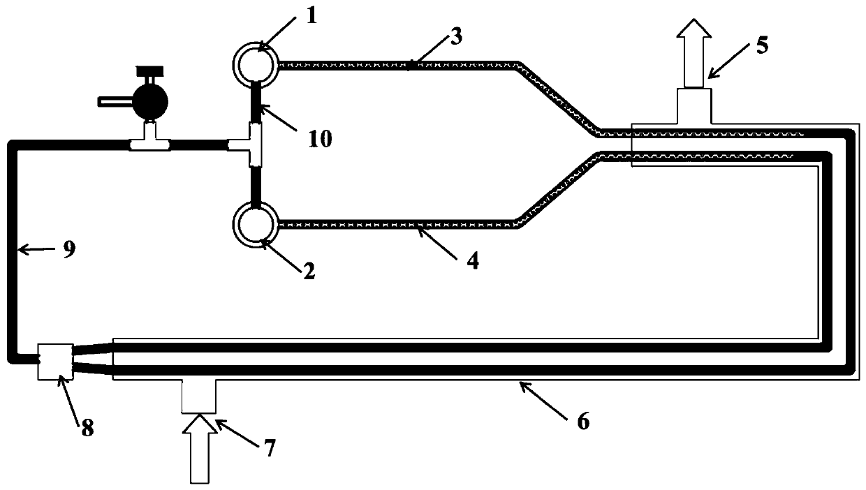
[0005] In view of the above defects or improvement needs of the prior art, the present invention provides a double evaporator loop heat pipe, in which the first evaporator and the second evaporator with independent steam transmission pipelines are designed in combination with the characteristics of the loop heat pipe itself. The evaporator, correspondingly, can effectively solve the problem of mutual interference between each evaporator, so it is especially suitable for applications with high heat flow and heat dissipation

Method used


Image

  • Double-evaporator loop heat pipe
  • Double-evaporator loop heat pipe
  • Double-evaporator loop heat pipe

Examples


Embodiment Construction

[0030] In order to make the object, technical solution and advantages of the present invention clearer, the present invention will be further described in detail below in conjunction with the accompanying drawings and embodiments. It should be understood that the specific embodiments described here are only used to explain the present invention, not to limit the present invention. In addition, the technical features involved in the various embodiments of the present invention described below can be combined with each other as long as they do not constitute a conflict with each other.

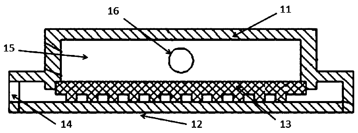
[0031] like figure 1 As shown, the embodiment of the present invention provides a double evaporator loop heat pipe, which includes a first evaporator 1, a second evaporator 2, a first vapor transmission line 3, a second vapor transmission line 4, and a condenser 6. Mixer 8 and liquid transfer pipeline 9, wherein: the first evaporator 1 and the second evaporator 2 are respectively connected to t...


PUM


Abstract

The invention belongs to the field of loop heat pipes, and particularly discloses a double-evaporator loop heat pipe. The double-evaporator loop heat pipe comprises a first evaporator, a second evaporator, a first steam transmission pipeline, a second steam transmission pipeline, a condenser, a mixer and a liquid transmission pipeline, wherein the first evaporator and the second evaporator are connected with an inlet of the condenser through the first steam transmission pipeline and the second steam transmission pipeline respectively; and a condensed liquid generated in the condenser is firstly mixed in the mixer and then is respectively fed into the first evaporator and the second evaporator through the liquid transmission pipeline, so that the double-evaporator loop heat pipe is formed.According to the invention, the requirement of large-area heat dissipation or heat dissipation of multiple heat sources can be met, and the heat dissipation efficiency of the loop heat pipe is effectively improved. Meanwhile, the independent steam transmission pipelines are adopted, the steam in the first evaporator and the second evaporator enters the condenser through the respective steam transmission pipelines, the interference between the evaporators is avoided, and the stability and operation controllability of the loop heat pipe are enhanced.

Description

technical field [0001] The invention belongs to the field of loop heat pipes, and more specifically relates to a double evaporator loop heat pipe. Background technique [0002] The loop heat pipe is a separate heat pipe, which has the advantages of large heat transfer, flexible pipeline layout, and no moving parts. It has broad application prospects in aerospace thermal control and ground high heat flow electronic device cooling. [0003] The loop heat pipe is mainly composed of an evaporator, a vapor / liquid transmission line, a condenser, etc. The capillary core is built into the evaporator, and forms a compensation cavity with the cavity between the shell of the evaporator. Its working principle is: one surface of the evaporator is closely attached to the wall of the equipment that needs to dissipate heat. When the equipment starts to work, the waste heat will heat the wall of the evaporator, and the heat will cause the working fluid in the evaporator to undergo a phase ch...

Claims


Application Information

Patent Timeline
IPC IPC(8): F28D15/04H05K7/20
CPCF28D15/043H05K7/20336
Inventor 刘志春何松邓为忠刘伟马钲沅
Owner HUAZHONG UNIV OF SCI & TECH
Learn More