
Heat exchange chamber of coke oven and coke oven

A coking oven and heat exchange chamber technology, applied in the field of coking, can solve problems such as unbalanced heating of coke ovens, self-sufficiency in heat, and influence on heat transfer effects, and achieve the goals of shortening coking time, fast heating speed, and improving heat exchange efficiency Effect

Pending Publication Date: 2020-04-10
HUATAI YONGCHUANG BEIJING TECH CO LTD
View PDF0 Cites 1 Cited by
  • Summary
  • Abstract
  • Description
  • Claims
  • Application Information

AI Technical Summary

Problems solved by technology

For the bedroom coke oven, due to the large floor space and high investment cost of the horizontal coke oven, the width of the coal cake is 3-4m, the too wide carbonization chamber seriously affects the heat transfer effect, the coking time is too long, and, Direct heating is often used, and 1.5-4% of coal and coke will be burned to supplement the heat required for coal dry distillation, resulting in a reduction in production capacity; for vertical coke ovens, due to the existing vertical (heat recovery) coke oven When the volatile content of coal is low, the heat required for coal carbonization cannot be self-sufficient, and additional gas is required for supplementary combustion, which makes the heating efficiency low. Moreover, due to the different coking periods of different carbonization chambers, the amount of raw gas produced Different, resulting in uneven heating of the coke oven and long coking time

Method used


Image

  • Heat exchange chamber of coke oven and coke oven
  • Heat exchange chamber of coke oven and coke oven
  • Heat exchange chamber of coke oven and coke oven

Examples


Embodiment 1

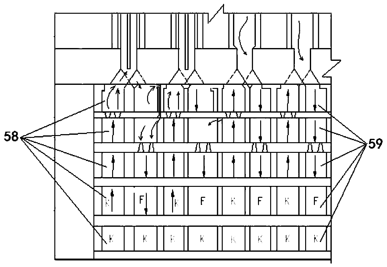
[0051] Such as figure 1 As shown, this embodiment discloses a heat exchange chamber for a coke oven, including a chamber body, the interior of the chamber body is a multi-layer structure, the interior of the chamber body is provided with an air passage 58 and a flue gas passage 59, the air passage 58 and the The flue gas channels 59 are arranged side by side and penetrated on the multi-layer structure at the same time, so that the layers of the multi-layer structure are connected in sequence, that is, each layer in the multi-layer structure has an air channel and a flue gas channel, and all The air passages of the layers are connected to form a whole row of air passages 58, and the smoke passages of all layers are connected to form a whole row of smoke passages 59, so that each layer of the multilayer structure has an air passage corresponding to the layer (which is A section of the whole row of air channels 58, hereinafter referred to as the air channel of the layer) and a sm...

Embodiment 2

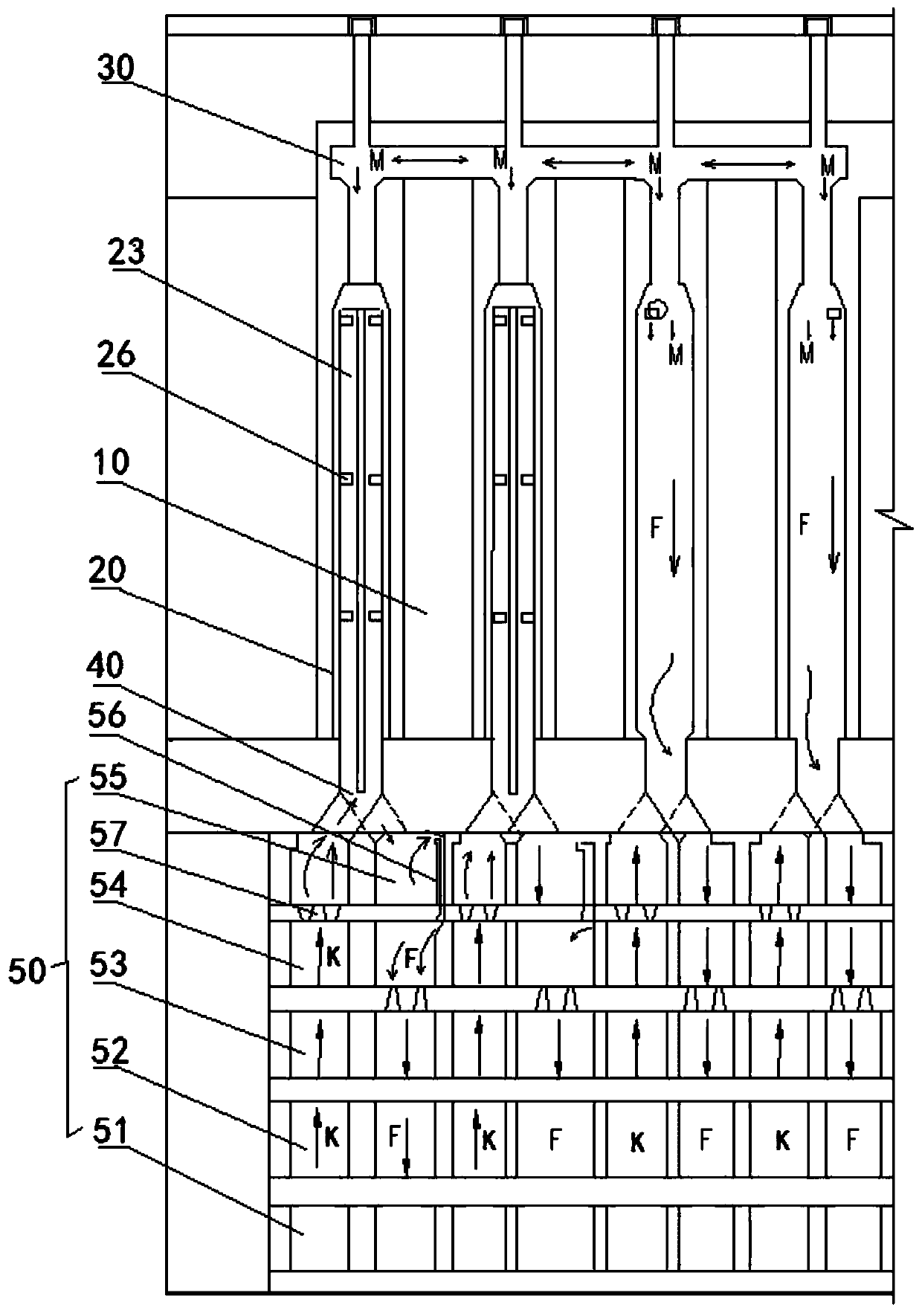
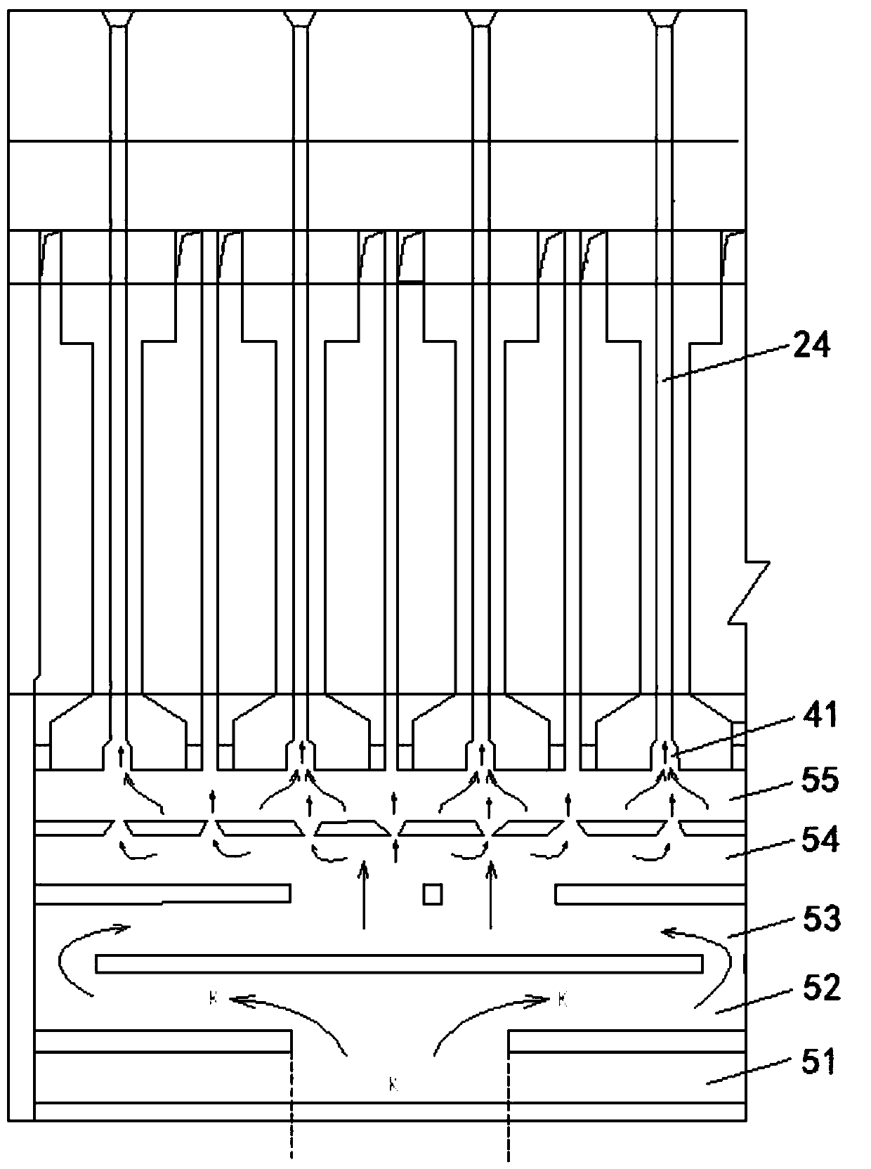
[0062] Such as figure 2 As shown, this embodiment discloses a coke oven, which includes a furnace body, which is provided with a carbonization chamber 10 and a combustion chamber 20, as well as the heat exchange chamber described in Embodiment 1. The carbonization chamber 10 and the combustion chamber 20 are arranged side by side on the upper part of the furnace body. The combustion chamber 20 includes a vertical fire passage 23 and an air passage 24. The carbonization chamber 10 communicates with the vertical fire passage 23. The heat exchange chamber 50 is located at the bottom of the furnace body. The air passage 58 communicates with the air passage 24 in the combustion chamber 20 , and its smoke passage 59 communicates with the vertical fire passage 23 in the combustion chamber 20 .

[0063] Optionally, the coke oven also includes a balance channel, which is arranged on the top of the carbonization chamber 10 and the combustion chamber 20, and communicates with the balanc...


PUM


Abstract

The invention discloses a heat exchange chamber of a coke oven. The heat exchange chamber of the coke oven comprises a chamber body, the interior of the chamber body is of a multi-layer structure, anair channel and a flue gas channel are arranged in each layer of the multi-layer structure in a penetrating mode, the layers of the multi-layer structure are sequentially communicated, the air channelis used for being communicated with the external environment, and the flue gas channel is used for being communicated with the external environment. And the flue gas channel is used for communicatingwith a vertical flame path of a combustion chamber in the coke oven. The invention also provides the coke oven adopting the heat exchange chamber. The heat exchange chamber is simple in structure, and the heat exchange efficiency of the coke oven can be effectively improved.

Description

technical field [0001] The invention belongs to the technical field of coking, and in particular relates to a heat exchange chamber and a coke oven including the heat exchange chamber. Background technique [0002] In the coking industry, when coking ovens are used for coking, the heat generated by raw coal gas and air combustion is usually used to heat the carbonization chamber to achieve carbonization of coal materials. [0003] Conventional regenerative coke ovens are currently equipped with a regenerator under the combustion chamber. The regenerator is used to preheat the combustion-supporting gas and raw coal gas at the same time, and then they are mixed in the combustion chamber for combustion. This regenerator The structure is complex, the heat exchange effect is poor, and the resistance to gas is large, the pressure drop is large, and gas leakage is prone to occur. At the same time, since the temperature of the combustion chamber can reach 1280°C-1400°C, the damage ...

Claims


Application Information

Patent Timeline
Patent Type & Authority Applications(China)
IPC IPC(8): C10B1/02C10B49/02C10B51/00
CPCC10B1/02C10B49/02C10B51/00
Inventor 姚梈徐列康健张晓光毛旸
Owner HUATAI YONGCHUANG BEIJING TECH CO LTD
Learn More