
Wear-resistant degating structure and mounting process thereof

An installation process and wear-resistant technology, applied in the field of molds, can solve the problems of incomplete finished products, dissatisfied products, low hardness, etc., and achieve the effects of increasing service life, improving bite force and stabilizing temperature

Pending Publication Date: 2020-04-10
CHENGDU LIANYU PRECISION MACHINERY
View PDF0 Cites 1 Cited by
  • Summary
  • Abstract
  • Description
  • Claims
  • Application Information

AI Technical Summary

Problems solved by technology

[0003] The conventionally designed nozzle tip in the industry is integral. During the working process, the molten plastic directly contacts the nozzle tip and fills the interior of the nozzle tip. Therefore, in order to prevent the molten material from cooling and solidifying, the nozzle tip is usually made of a material with a high thermal conductivity. Such as beryllium copper, but beryllium copper has low hardness and poor impact resistance. It is easy to deform and wear under long-term use, which will change the size of the outlet. The size of the outlet is the most critical factor determining the quality of the gate. The size of the outlet must be stable within the design error range to produce good products
If the size of the discharge port is too large (that is, the gap is large), when the mold is opened and the product is separated, the residual plastic in the gap is easily taken out near the gate, resulting in gate wire drawing; the size of the discharge port is too small, and the material flow is difficult. The product is dissatisfied, that is, the finished product is incomplete; the size of the outlet is unstable, which eventually leads to unstable product gate quality, which seriously affects product quality

Method used


Image

  • Wear-resistant degating structure and mounting process thereof
  • Wear-resistant degating structure and mounting process thereof
  • Wear-resistant degating structure and mounting process thereof

Examples


Embodiment Construction

[0031] The technical solutions of the present invention will be clearly and completely described below in conjunction with the embodiments. Apparently, the described embodiments are only some of the embodiments of the present invention, not all of them. Based on the embodiments of the present invention, all other embodiments obtained by those skilled in the art without making creative efforts belong to the protection scope of the present invention.

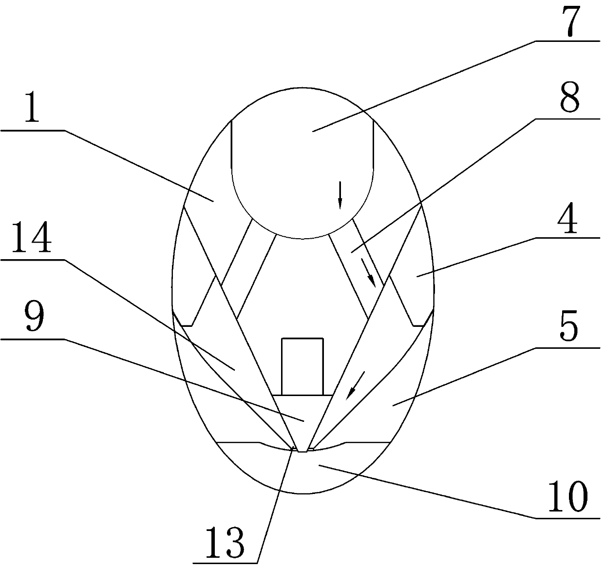
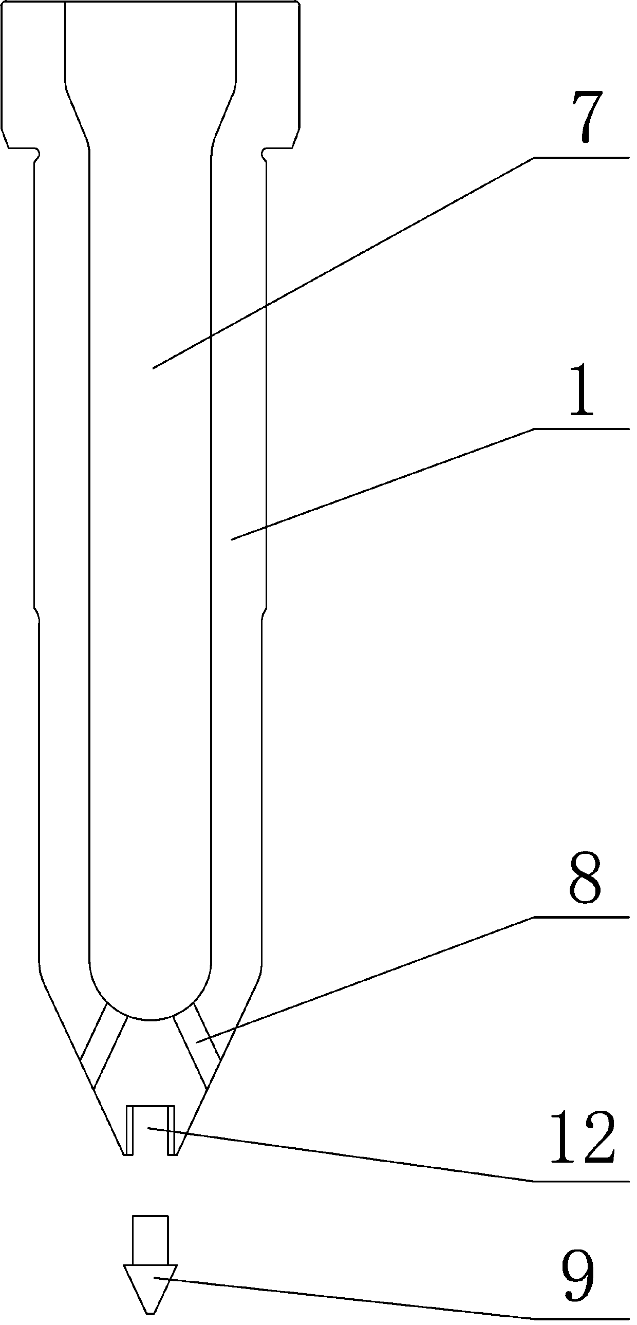
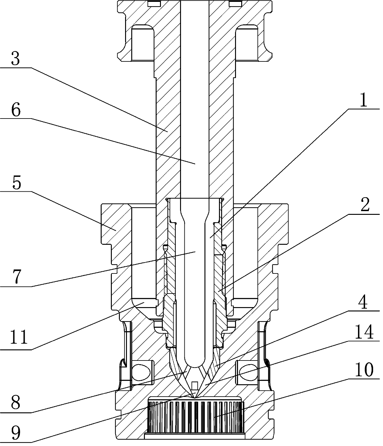
[0032] refer to Figure 1-3 , the present invention provides a technical solution:

[0033] A wear-resistant glue punching structure, comprising a gate mold core 5 and a nozzle tip 1 cooperatingly installed in the gate mold core 5, the nozzle tip 1 is provided with a through glue punching channel, and the gate mold core 5 A gap 14 is formed between the nozzle tip 1, the gap 14 communicates with the glue channel, and the gap 14 forms a discharge port 13 with a stable flow rate, and the gap 14 gradually narrows toward the discharge...


PUM

PropertyMeasurementUnit
Diameteraaaaaaaaaa

Abstract

The invention discloses a wear-resistant degating structure. The wear-resistant degating structure comprises a gate mold core and a nozzle tip arranged in the gate mold core in a matched mode, whereina through degating channel is formed in the nozzle tip, a gap is formed between the gate mold core and the nozzle tip, and the gap communicates with the degating channel; a discharge port with stableflow is formed in the gap, and the gap gradually narrows towards the direction of the discharge port; and the end part of the nozzle tip is provided with a conical part, a wear-resistant tip is arranged on the conical part, generatrix of the wear-resistant tip is collinear with generatrix of the conical part, and the hardness of the wear-resistant tip and the hardness of the gate mold core are both greater than that of the nozzle tip. The wear-resistant tip is arranged at the end part of the nozzle tip, so that the hardness and the wear resistance of the end part of the nozzle tip are greatlyimproved on the premise of not influencing the overall heat conductivity of the nozzle tip, and the size of the discharge port is ensured, so that the flow of the discharge port is stable, the product quality is greatly improved and the service life of the degating structure is greatly prolonged.

Description

technical field [0001] The invention relates to the field of molds, in particular to a wear-resistant glue punching structure and an installation process thereof. Background technique [0002] With the development of society and the improvement of people's living standards, consumers have higher and higher requirements for daily necessities. Therefore, in the production of products, the requirements for gate traces of products are also higher and higher, especially in some special fields, such as In the medical and food industries, the requirements for gate traces are even higher. [0003] The conventionally designed nozzle tip in the industry is integral. During the working process, the molten plastic directly contacts the nozzle tip and fills the interior of the nozzle tip. Therefore, in order to prevent the molten material from cooling and solidifying, the nozzle tip is usually made of a material with a high thermal conductivity. Such as beryllium copper, but beryllium c...

Claims


Application Information

Patent Timeline
IPC IPC(8): B29C45/27B29C33/30
CPCB29C45/1742B29C45/27B29C45/278B29C2045/2766
Inventor 王巍
Owner CHENGDU LIANYU PRECISION MACHINERY
Learn More