
Light source coupled irradiation device for hair growth

An irradiation device and light source technology, which is applied in the field of weak laser applications, can solve the problems of poor uniformity of irradiation, uneven laser energy, and low laser utilization efficiency, and achieve the effect of convenient and precise fine-tuning and improvement of utilization efficiency

Pending Publication Date: 2020-04-10
SUZHOU INST OF BIOMEDICAL ENG & TECH CHINESE ACADEMY OF SCI
View PDF0 Cites 0 Cited by
  • Summary
  • Abstract
  • Description
  • Claims
  • Application Information

AI Technical Summary

Problems solved by technology

However, the hair growth products that have been developed at present all directly irradiate the head without shaping the light source. There are two disadvantages in this scheme: one is that the uniformity of the irradiation is very poor due to the different divergence angles of the long and short axes of the semiconductor laser. The second is that there is a certain distance between the light source and the scalp. For moderate and mild hair loss patients, the non-necrotic hair will block and absorb the laser, resulting in low utilization efficiency of the laser and increasing the laser energy irradiated to the scalp. The non-uniformity, therefore, needs to be further optimized

Method used


Image

  • Light source coupled irradiation device for hair growth
  • Light source coupled irradiation device for hair growth
  • Light source coupled irradiation device for hair growth

Examples


Embodiment 1

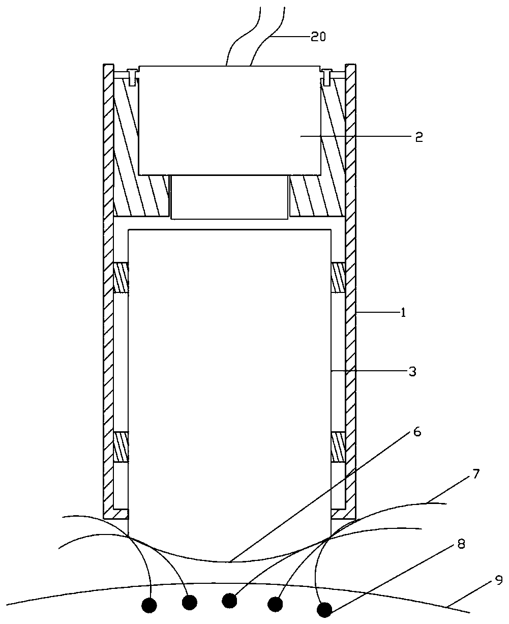
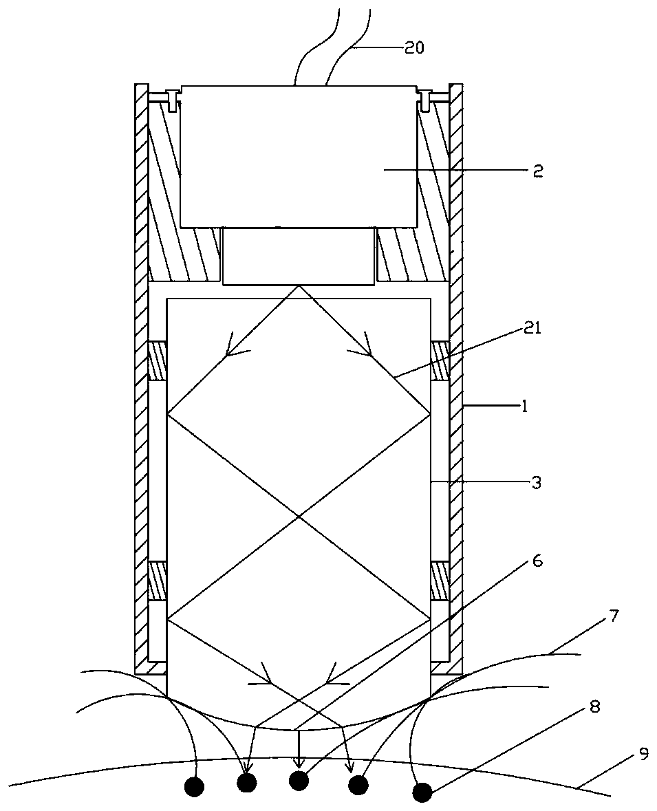
[0050] refer to figure 1 and 2 , in this embodiment, the spot shaping element is a light guide mirror 3 fixed in the sleeve 1 , and the lower end of the light guide mirror 3 forms an arc-shaped exit end surface 6 . Light guide mirror 3,4 material can be glass or plastics.

[0051] The upper and lower ends of the light guide mirror 3 are coated with an anti-reflection film that is highly transparent to the output wavelength of the light source 2 to increase the transmittance of the emission wavelength, and its cross section can be designed as a rectangle or a circle according to the divergence angle of the light source 2 . This scheme utilizes the principle of total reflection. Through theoretical calculations, adjusting the parameters of the light guide mirror 3 and the distance between the light guide mirror 3 and the light source 2 can make the emitted light 21 undergo multiple total reflections on the side wall of the light guide mirror 3 , and finally in the arc shape o...

Embodiment 2

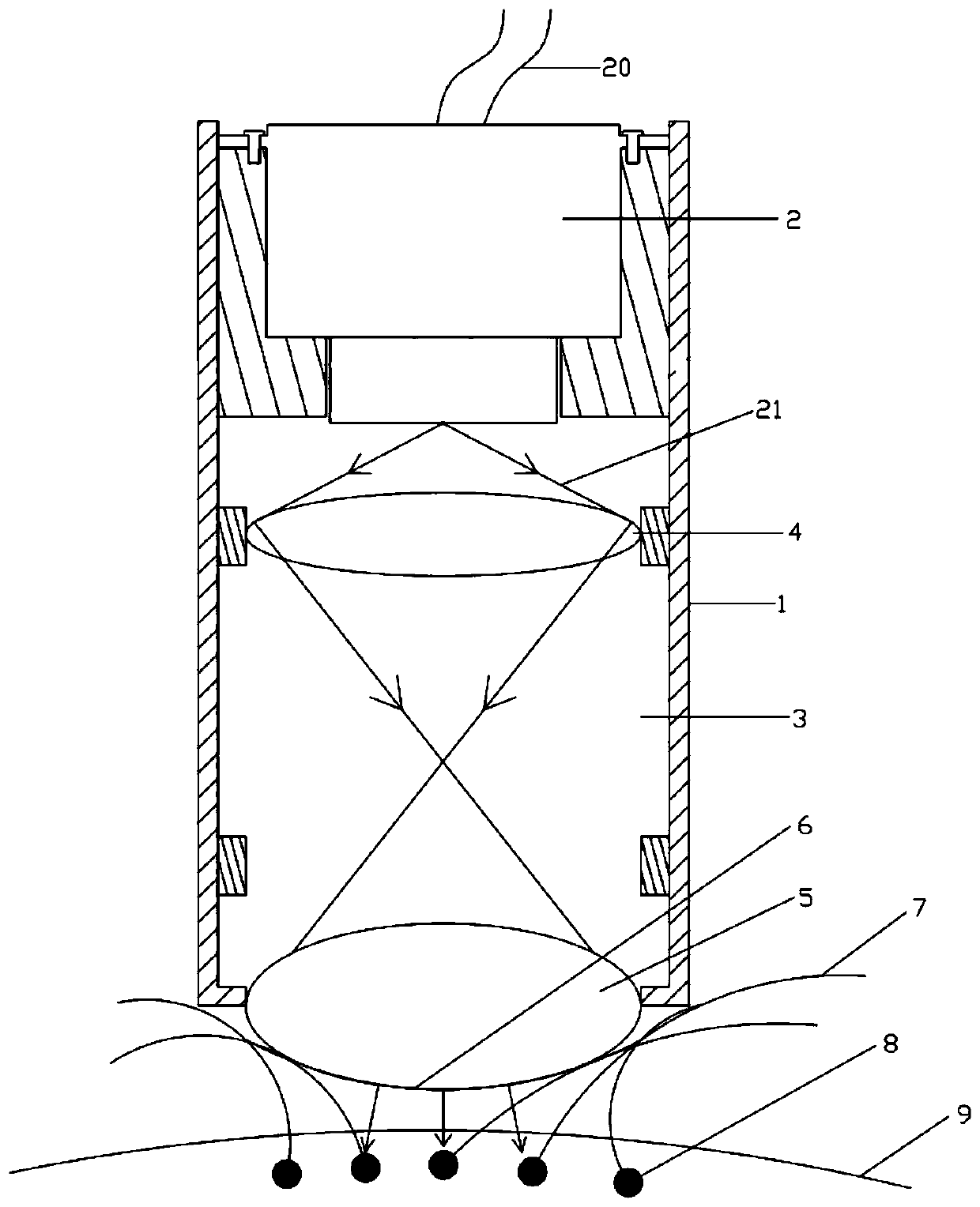
[0053] refer to image 3 , in this embodiment, the spot shaping element includes several lenses arranged sequentially along the exit optical path of the light source 2 , and the lower surface of the lens at the end of the optical path forms an arc-shaped exit end surface 6 . The upper and lower optical surfaces of the lens are coated with an anti-reflection film with high transmittance to the output wavelength of the light source 2 to increase the transmittance of the emission wavelength. The lens material can be glass or plastic.

[0054] Further, the lens includes a first lens 4 and a second lens 5 sequentially arranged along the outgoing light path of the light source 2 . According to the divergence angle of the light source 2, the first lens 4 can be an aspherical lens or a spherical lens, so as to facilitate the homogenization of the light spot. This solution utilizes the principle of transmission. Through theoretical calculation, the distance between the first lens 4 a...

Embodiment 3

[0056] refer to Figure 4-11 , in this embodiment, the casing 1 is further optimized. A light source installation sleeve 10 is fixedly connected to the inner wall of the sleeve 1 , and a light source adjustment sleeve 11 is arranged in the light source installation sleeve 10 to move up and down along the axial direction of the sleeve 1 , and the light source 2 is fixedly connected in the light source adjustment sleeve 11 . The up and down position of the light source 2 can be finely adjusted through the light source adjustment sleeve 11, so as to facilitate the adjustment of the light path. When designing this device, it is necessary to pre-design the distance between the light output end of the light source 2 and the spot shaping element below (the upper surface of the light guide mirror 3 or the upper surface of the first lens 4), but due to processing or installation errors, After installation, there may be errors in a small range. At this time, through the light source ad...


PUM

PropertyMeasurementUnit
Wavelengthaaaaaaaaaa

Abstract

The invention discloses a light source coupled irradiation device for hair growth. The light source coupled irradiation device comprises a sleeve, a light source arranged in the sleeve and a light spot shaping element arranged in the sleeve and used for shaping the light emitted by the light source. A light-emitting end of the light spot shaping element is provided with an arc-shaped light-emitting end face, and the arc-shaped light-emitting end face extends out of an opening formed in the lower end of the sleeve. The light emitted by the light source is shaped and homogenized through the light spot shaping element and then is emitted to the scalp, more ATP (adenosine triphosphate) is generated by cell mitochondria of hair follicles under the scalp due to stimulation of irradiation light,energy and nutrition are generated from inside to outside, the nutrients are continuously provided for the hair follicles, necrotic hair follicles are repaired, and the purpose of hair growth is achieved. The light spot shaping element can homogenize the light spots, the arc-shaped emergent end face at the tail end of the light spot shaping element can separate hair to guide treatment light to the scalp, the light source is prevented from being blocked and absorbed by the hair, and the utilization efficiency of the light source is greatly improved.

Description

technical field [0001] The invention relates to the technical field of weak laser application, in particular to a light source coupling irradiation device for hair growth. Background technique [0002] In 1967, Mester of Hungary discovered for the first time the biological effects of low level laser therapy (LLLT) acting on biological tissues. Since then, many scholars have conducted in-depth research on its mechanism and curative effect in treating diseases through animal and clinical experiments, and proposed Low level laser light (LLLT) therapy. In the 1970s, the former Soviet Union made more in-depth research on the mechanism and effects of weak laser irradiation on organisms, and developed various therapeutic instruments. At present, various weak laser irradiation treatment equipment has entered the practical stage. China, Europe, the United States, Japan and other countries have widely used weak laser treatment equipment in health care, medical treatment, beauty, etc....

Claims


Application Information

Patent Timeline
IPC IPC(8): A61N5/067
CPCA61N5/0617A61N2005/0626A61N2005/0632A61N2005/0651A61N2005/0664A61N5/067
Inventor 高静田玉冰姚文明陈建生王鹏
Owner SUZHOU INST OF BIOMEDICAL ENG & TECH CHINESE ACADEMY OF SCI
Learn More