Optical detection device of multi-channel real-time fluorescence detector

A real-time fluorescence and optical detection technology, applied in the field of fluorescence detection, can solve the problems of poor sensitivity, large detection structure volume, complex mechanical structure, etc., and achieve the effects of improving detection sensitivity, high excitation light intensity, and reducing volume

Inactive Publication Date: 2020-04-07
INST OF ANALYSIS GUANGDONG ACAD OF SCI (CHINA NAT ANALYTICAL
View PDF6 Cites 9 Cited by
  • Summary
  • Abstract
  • Description
  • Claims
  • Application Information

AI Technical Summary

Problems solved by technology

[0003] In the current technology, some of them use mechanical scanning devices to realize the detection of multiple channels, but the mechanical structure is complex and bulky, and the scanning speed is also limited; some of them use lens groups to image and then use CCD for detection, which has poor sensitivity and inter-channel interference. At the same time, due to the volume and focal length constraints of the lens group, the volume of the entire detection structure is relatively large
[0004] On the other hand, in the current technology, some of them use the method of detecting the upper part of the sample tube, which requires the upper cover of the instrument to open or set a transparent window, which is not conducive to the design of the thermal cover, and the thermal cover is mainly used for heating the top of the sample tube , so as to avoid the condensation of the sample on the top of the sample tube and reduce the evaporation of the sample, which is of great significance to the accuracy of the detection; some of them use the bottom plate detection method, which is very easy to cause detection when the sample leaks or the operation is wrong. However, the small volume of the PCR sample tube makes it difficult to clean the contamination, which affects the subsequent detection

Method used


Image

  • Optical detection device of multi-channel real-time fluorescence detector
  • Optical detection device of multi-channel real-time fluorescence detector
  • Optical detection device of multi-channel real-time fluorescence detector

Examples


Embodiment 1

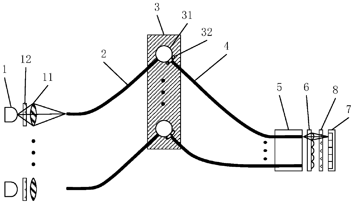
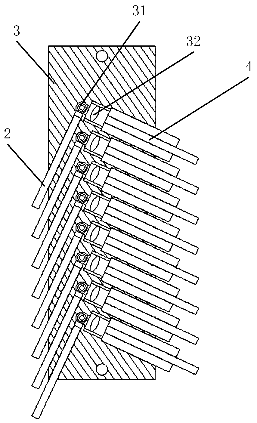
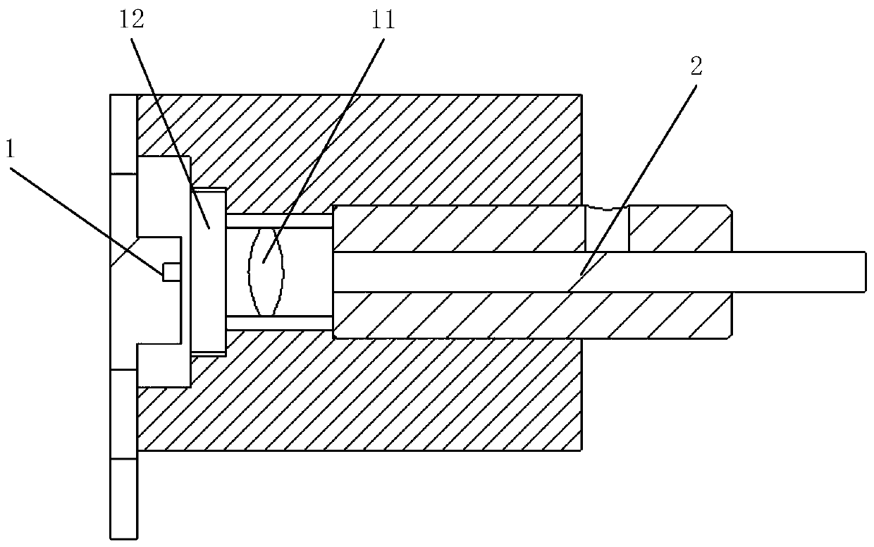
[0024] Such as Figure 1~4 , an optical detection device of a multi-channel real-time fluorescence detector, comprising an excitation light source 1, an excitation optical fiber 2, a sample block 3, an emission optical fiber 4, an emission optical fiber module 5, a microlens array 6, an emission filter 8 and a fluorescence The detector array 7; the sample block 3 is provided with a plurality of sample holes 31, and each sample hole 31 is provided with a sample tube for placing a test.

[0025] Each sample hole 31 is provided with an excitation fiber 2 and a launch fiber 4. In this embodiment, the excitation fiber 2 and the launch fiber 4 are all arranged on the side of the sample hole 31, avoiding the top of the sample tube. Or bottom detection, without affecting the design of the thermal cover, avoiding the problem of detector contamination; the excitation fiber 2 and the emission fiber 4 are set on the same horizontal plane, and the angle a between the excitation fiber 2 and...


PUM


Abstract

The invention discloses an optical detection device of a multichannel real-time fluorescence detector. The optical detection device comprises a sample block. A plurality of sample holes for placing sample tubes for detection are formed in the sample block. Each sample hole is correspondingly provided with an excitation optical fiber and a transmitting optical fiber. The excitation optical fibers are arranged on one side of the sample hole. The emission optical fibers are arranged on the other side of the sample hole, the excitation optical fibers are connected with the excitation light sources, each excitation optical fiber is correspondingly connected with one excitation light source, and the emission optical fibers are sequentially connected with the emission optical fiber light emittingmodule, the micro lens array and the fluorescence detector array. The excitation optical fiber and the emission optical fiber are arranged on the side face of the sample hole, detection on the upperportion or the bottom of the sample tube is not needed, design of the hot cover is not affected, and pollution of the detector is avoided.

Description

technical field [0001] The invention relates to the technical field of fluorescence detection, in particular to an optical detection device of a multi-channel real-time fluorescence detector. Background technique [0002] Real-time fluorescent detectors, especially real-time fluorescent PCR detectors, are the main tools for biological detection. In real-time fluorescent PCR, a DNA probe containing a fluorescent group is added to the reaction reagent. During the DNA amplification process, the intensity of the emitted fluorescence generated by excitation increases with the increase of the target DNA product. Therefore, the real-time fluorescent PCR detector can determine the presence and quantity of target DNA by detecting the intensity of fluorescence emitted during the amplification process. [0003] In the current technology, some of them use mechanical scanning devices to realize the detection of multiple channels, but the mechanical structure is complex and bulky, and th...

Claims


Application Information

Patent Timeline
IPC IPC(8): G01N21/64G01N21/01
CPCG01N21/6428G01N21/6454G01N21/01
Inventor 张冠文刘日威倪树标梁伟能黎国标卢雅琳王李笛
Owner INST OF ANALYSIS GUANGDONG ACAD OF SCI (CHINA NAT ANALYTICAL
Why Eureka
Try Eureka