
Positioning and guiding device for on-site cutting detection of adhesive force of metal structure coating

A metal structure, positioning-oriented technology, applied in the field of machinery, can solve the problems of increasing the detection time, evaluation, easy to scratch, etc., and achieve the effect of shortening the detection time, convenient switching, and simple structure

Pending Publication Date: 2020-04-07
ZHEJIANG INST OF HYDRAULICS & ESTUARY
View PDF1 Cites 0 Cited by
  • Summary
  • Abstract
  • Description
  • Claims
  • Application Information

AI Technical Summary

Problems solved by technology

The steel ruler is used for positioning during the on-site inspection, and the spacing and angle between the cutting lines inevitably deviate from the specification requirements, which affects the evaluation of the inspection results
[0005] 2. The positioning of cutting lines is cumbersome
Directly use the steel ruler and cutter to position and cut, and a lot of effort is devoted to the measurement of the cutting position and angle, which greatly increases the detection time
[0006] 3. There are hidden dangers in the cutting process
The right hand holds the knife and scratches hard to the metal base, which is very easy to scratch the left hand holding the ruler for positioning

Method used


Image

  • Positioning and guiding device for on-site cutting detection of adhesive force of metal structure coating
  • Positioning and guiding device for on-site cutting detection of adhesive force of metal structure coating
  • Positioning and guiding device for on-site cutting detection of adhesive force of metal structure coating

Examples


Embodiment Construction

[0031] Further description will be given below in conjunction with the embodiments shown in the accompanying drawings.

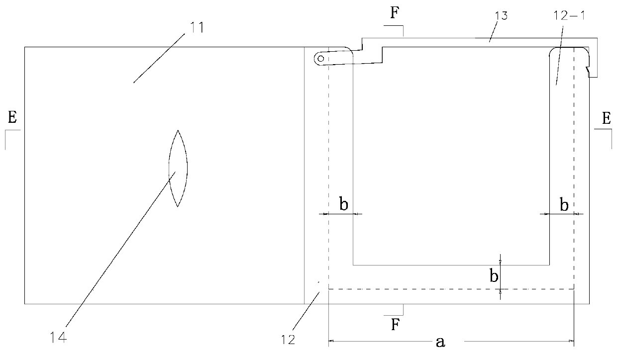
[0032] The embodiment shown in the accompanying drawings is a positioning guide device for on-site cutting detection of metal structure coating adhesion, including a magnetic base 11 (conventional component) and a guide card. Two retaining strips 15 ( image 3 The middle display is a trapezoidal bar), suitable for installation and fixation on conventional planes and surfaces to be inspected on many curved surfaces.

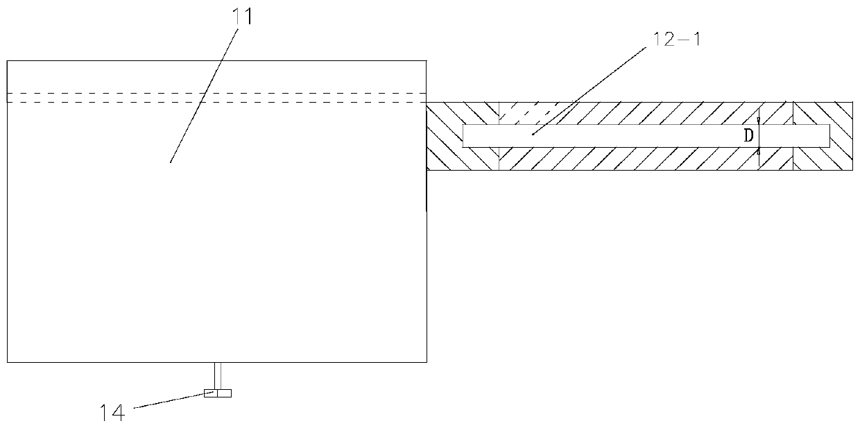
[0033] A card slot frame 12 is integrally cast and connected with the magnetic base; the card slot frame is a fence structure with one end open, and the opening of the card slot frame is equipped with a lock assembly for fastening the guide card; the lock assembly is preferably Non-magnetic metal material, easy to open and close when the magnetic base is magnetic. A U-shaped slot 12-1 is made along the inner edge of the fence (the groove depth...


PUM

PropertyMeasurementUnit
thicknessaaaaaaaaaa
thicknessaaaaaaaaaa

Abstract

The invention relates to the field of machinery and aims to provide a positioning and guiding device for on-site cutting detection of adhesive force of a metal structure coating. The device can accurately, quickly and safely carry out field detection on the adhesive force of the coating, so that the strictness of the test process is ensured, the potential safety hazard in the test process is eliminated, and the detection efficiency is effectively improved; meanwhile, the device has portability and universality and is suitable for being used in various complex engineering sites. According to the technical scheme, the positioning and guiding device for field cutting detection of the adhesive force of the metal structure coating comprises a magnetic base and a guiding clamping piece; the device is characterized in that one side of the magnetic base is fixedly connected with a clamping groove frame; the clamping groove frame is of a fence structure with an opening in one end, a U-shaped inserting groove is formed along the edge of the inner side of the fence, and a guide clamping piece is inserted from the opening of the clamping groove frame and matched with the U-shaped inserting groove in an inserted and embedded mode. A lock catch assembly used for fastening the guide clamping piece is installed at an opening of the clamping groove frame.

Description

technical field [0001] The invention relates to the field of machinery, in particular to a positioning and guiding device for on-site testing of metal structure coating adhesion. Background technique [0002] The detection methods of metal structure coating adhesion can be summarized into two categories: drawing method and cutting method. The pulling method uses special equipment to quantitatively detect the pulling force required to separate the coating per unit area from the substrate. The cutting method uses a knife to cut from the coating surface to the metal substrate, and then uses a pressure-sensitive tape to peel off or a knife to pick and peel to qualitatively evaluate the bonding strength of the coating. The cutting method is widely used in the detection of metal structure coating adhesion due to its short detection period and simple operation. [0003] The test of coating adhesion cutting method is divided into the test of the coating of the small test plate com...

Claims


Application Information

Patent Timeline
Patent Type & Authority Applications(China)
IPC IPC(8): G01N19/04
CPCG01N19/04
Inventor 张新春王良苏玉杰曹敏陈秀良陈式华王丰平仇涛武利强谢中凯苏全马庆宏高海峰李浩俞人杰张奕峰施彦丰程武王志萌邹琨方珲赵刚唐战
Owner ZHEJIANG INST OF HYDRAULICS & ESTUARY
Learn More