Electro-optical modulator based on metal-medium-metal waveguide
An electro-optic modulator and metal technology, which is applied in instruments, optics, nonlinear optics, etc., can solve the problem that the metal-dielectric-metal waveguide mode cannot be adjusted
- Summary
- Abstract
- Description
- Claims
- Application Information
AI Technical Summary
Problems solved by technology
Method used
Image

Examples
Embodiment 1
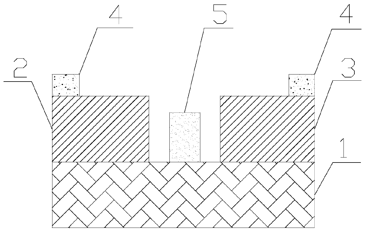
[0028] figure 1 It is a schematic diagram of an electro-optic modulator based on a metal-dielectric-metal waveguide Figure 1 . figure 1 A cross-sectional view of the waveguide. Such as figure 1 As shown, the waveguide includes a substrate 1 , a first metal block 2 , a second metal block 3 , an electrode 4 , and an electro-optic crystal 5 . Wherein, the substrate 1 is made of silicon dioxide material, the first metal block 2 and the second metal block 3 are made of gold material, the electro-optic crystal 5 is any one of zinc sulfide, copper carbide, gallium arsenide, and gallium phosphide, and the electrode 4. Connect the first metal block 2 and the second metal block 3. As a metal-dielectric-metal waveguide, the energy of electromagnetic waves is mainly concentrated in the dielectric layer between the first metal block 2 and the second metal block 3. The waveguide has the characteristics of small mode area and less susceptible to external influence on propagation charact...
Embodiment 2
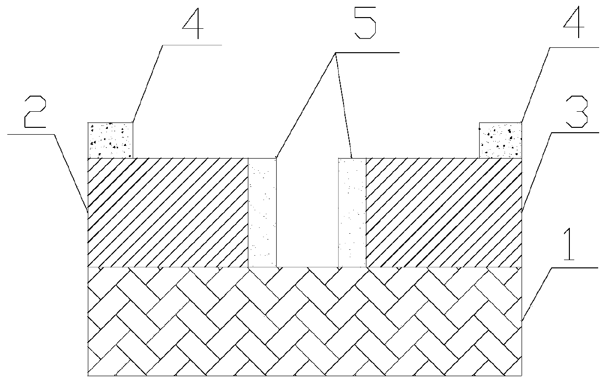
[0032] image 3 It is another schematic diagram of an electro-optic modulator based on a metal-dielectric-metal waveguide Figure II . On the basis of Example 1, such as image 3 As shown, the number of electro-optic crystals 5 is two, and the two electro-optic crystals 5 are in contact with the first metal block 2 and the second metal block 3 respectively. At this time, the electric field will be concentrated in a small area between the two electro-optic crystals 5, reducing the mode area of the waveguide. When the refractive index of the electro-optic crystal 5 changes, the change of the effective refractive index of the waveguide is larger, that is, the adjustment range is larger.
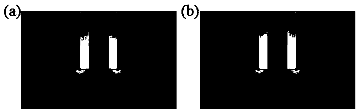
[0033] Figure 4 is at different refractive indices of electro-optic crystals, image 3 Electric field distribution diagram of the metal-dielectric-metal waveguide section shown. Figure 4 a is the electric field distribution diagram when the refractive index of the electro-optic crystal...
Embodiment 3
[0036] Figure 5 It is a schematic diagram of another electro-optic modulator based on metal-dielectric-metal waveguide Figure three . On the basis of Example 2, such as Figure 5 As shown, the bottoms of the two electro-optic crystals 5 are also provided with communication parts. In this way, the two electro-optic crystals 5 are connected through the communication part. The connected electro-optic crystal 5 and the substrate form an enclosing area, where electromagnetic waves are gathered to form a confinement area for electromagnetic waves, further reducing the mode area of the waveguide. When the refractive index of the electro-optic crystal 5 changes, the change of the effective refractive index of the waveguide is larger, that is, the adjustment range is larger.
[0037] Figure 6 is at different refractive indices of electro-optic crystals, Figure 5 Electric field distribution diagram of the metal-dielectric-metal waveguide section shown. Figure 6 a is the el...
PUM
| Property | Measurement | Unit |
|---|---|---|
| refractive index | aaaaa | aaaaa |
| refractive index | aaaaa | aaaaa |
| refractive index | aaaaa | aaaaa |
Abstract
Description
Claims
Application Information
 - R&D
- Intellectual Property
- Life Sciences
- Materials
- Tech Scout
- Unparalleled Data Quality
- Higher Quality Content
- 60% Fewer Hallucinations
Browse by: Latest US Patents, China's latest patents, Technical Efficacy Thesaurus, Application Domain, Technology Topic, Popular Technical Reports.
© 2025 PatSnap. All rights reserved.Legal|Privacy policy|Modern Slavery Act Transparency Statement|Sitemap|About US| Contact US: help@patsnap.com