Copper foil and current collector of energy storage device
A technology of electrolytic copper foil and current collector, which is applied in the field of current collectors, can solve problems such as difficult to meet the high strength requirements of lithium battery foil, and achieve the effect of not easy to soften and crack, and high conductivity
- Summary
- Abstract
- Description
- Claims
- Application Information
AI Technical Summary
Problems solved by technology
Method used
Image


Examples
experiment example 1
[0034] First prepare the basic electrolyte (sulfuric acid-copper sulfate electrolyte), which contains copper ions: 90g / L, sulfuric acid: 45g / L and chloride ions 30ppm, and add 10mL / L crystal surface modifier and 5mL / L gloss agent As an additive, the crystal surface modifying agent is a commercially available crystal surface modifying agent (manufacturer: Tianhong, product number ECD731), and the gloss agent is also a commercially available gloss agent (manufacturer: Tianhong, product number GR891).
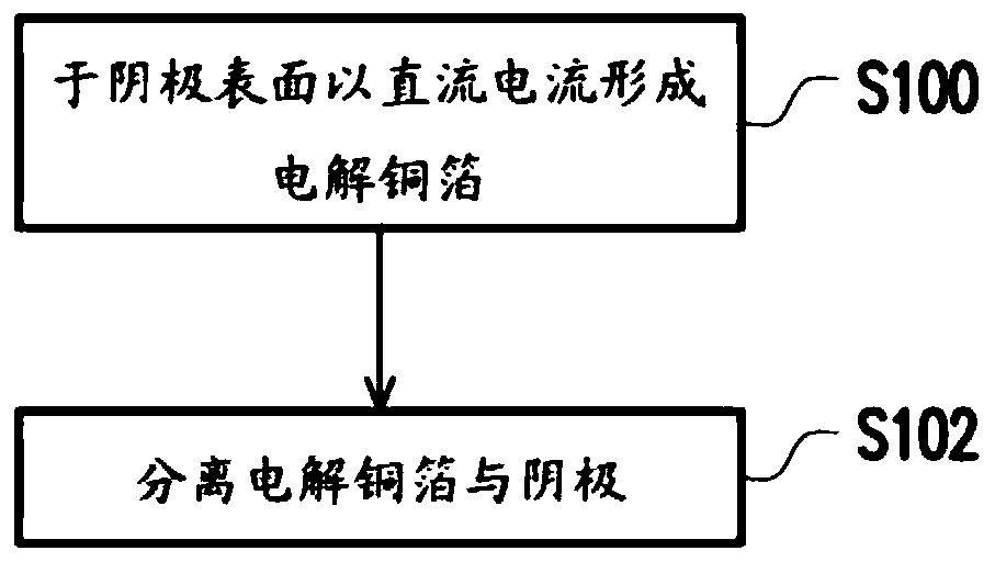
[0035] A rotating electrode device (grinding and polishing) titanium wheel is used as the cathode, and the anode is an insoluble anode (DSA), and a DC power supply is used, and the cathode is soaked in the electrolyte for 40 seconds, and then the current density is 40ASD. The liquid temperature is 40°C and the electrode rotation speed is 700rpm, and an electrolytic copper foil with a thickness of 8 μm is directly formed on the surface of the titanium wheel.
[0036]After the elect...
experiment example 2
[0038] Prepare basic electrolyte (sulfuric acid-copper sulfate electrolyte), which contains copper ion: 90g / L, sulfuric acid: 45g / L and chloride ion 30ppm, and adds the above-mentioned crystal plane modifying agent of 40mL / L and the above-mentioned luster of 2mL / L agents as additives.
[0039] Use the same electrolysis device as in Experimental Example 1, and first soak the cathode in the electrolyte for 40 seconds, then directly form an electrolytic copper foil with a thickness of 8 μm on the surface of the titanium wheel with a current density of 40ASD, an electrolyte temperature of 40°C and an electrode speed of 700rpm. .
[0040] After the electrolysis is completed, the electrolytic copper foil is separated from the titanium wheel, and subsequent corresponding tests are carried out. The test results are shown in Table 1 below.
experiment example 3
[0042] Prepare basic electrolyte (sulfuric acid-copper sulfate electrolyte), which contains copper ion: 90g / L, sulfuric acid: 45g / L and chloride ion 30ppm, and adds the above-mentioned crystal surface modifier of 40mL / L and the above-mentioned luster of 5mL / L agents as additives.
[0043] Use the same electrolysis device as in Experimental Example 1, and first soak the cathode in the electrolyte for 40 seconds, then directly form an electrolytic copper foil with a thickness of 8 μm on the surface of the titanium wheel with a current density of 40ASD, an electrolyte temperature of 40°C and an electrode speed of 700rpm. .
[0044] After the electrolysis is completed, the electrolytic copper foil is separated from the titanium wheel, and subsequent corresponding tests are carried out. The test results are shown in Table 1 below.
PUM
| Property | Measurement | Unit |
|---|---|---|
| Temperature tensile strength | aaaaa | aaaaa |
| Thickness | aaaaa | aaaaa |
Abstract
Description
Claims
Application Information
 - R&D
- Intellectual Property
- Life Sciences
- Materials
- Tech Scout
- Unparalleled Data Quality
- Higher Quality Content
- 60% Fewer Hallucinations
Browse by: Latest US Patents, China's latest patents, Technical Efficacy Thesaurus, Application Domain, Technology Topic, Popular Technical Reports.
© 2025 PatSnap. All rights reserved.Legal|Privacy policy|Modern Slavery Act Transparency Statement|Sitemap|About US| Contact US: help@patsnap.com