Distributed braking system with parking function and braking pressure vector control method thereof
A brake system and brake controller technology, which is applied in the direction of brake safety system, brake transmission device, brake action activation device, etc., can solve the problem that the brake system no longer meets the braking needs of smart cars and new energy vehicles And other issues
- Summary
- Abstract
- Description
- Claims
- Application Information
AI Technical Summary
Problems solved by technology
Method used
Image
Examples
Embodiment 1
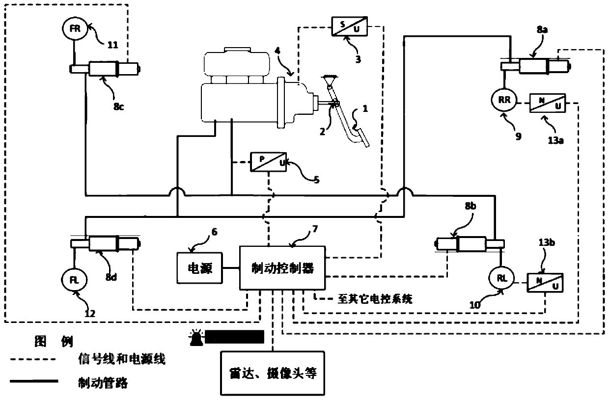
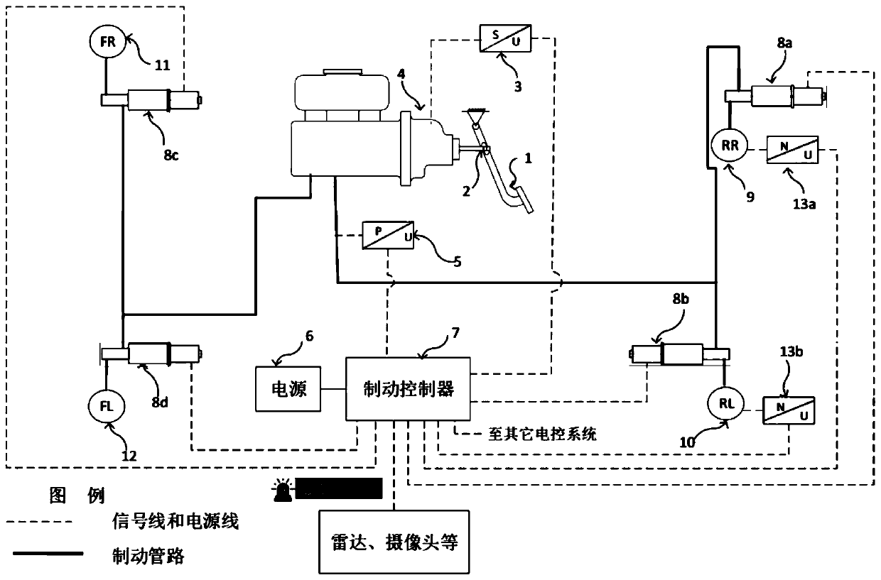
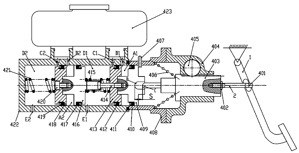
[0066] Such as Figure 1 to Figure 5 As shown, the present invention provides a distributed brake system with parking function and its brake pressure vector control method, which mainly includes a brake pedal 1, a human cylinder 4, a brake controller 7 and a power supply 6, and also includes at least Three electric cylinders electrically connected to the brake controller 2, the electric cylinders are respectively connected to the drain holes 416 of the manpower cylinder 4 through brake pipelines, and the electric cylinders are connected to the automobile The same number of wheel brakes, and each electric cylinder forms a brake circuit with a corresponding wheel brake. The brake controller 7 is respectively connected with the pedal travel sensor 3 and the pressure sensor 5 through a signal line, and is used for measuring the stroke of the brake pedal 1 and the pressure of the human cylinder 4; The support pin 2 is connected with the human cylinder 4; the brake controller 7 is ...
Embodiment 2
[0111] The internal structure of the electric cylinder in the first embodiment can also be set as Figure 4 and Figure 5 The electric cylinder shown; in this embodiment, other parts except the electric cylinder are consistent with the first embodiment.
[0112] Such as Figure 6 and Figure 7 As shown, the electric cylinder includes a motor 201 and a housing connected to the motor 201 , and also includes: a connecting rod 213 connected to the motor 201 through a worm gear mechanism, and a piston part rotationally connected to the connecting rod 213 .
[0113] The housing includes a motor housing 205 connected to the 201 motor, a worm gear housing 221 connected to the motor housing 205, and a cylinder block 224 connected to the worm gear housing 221; The liquid supply hole F is radially provided with a liquid discharge hole E on the lower inner wall of the cylinder body 224 ; the liquid supply hole F communicates with the liquid discharge hole 416 of the human cylinder 4 th...
Embodiment 3
[0135] The electric cylinders in Embodiment 1 and Embodiment 2 can also be set as double-chamber electric cylinders in this embodiment; the cylinder body 217 part of the double-chamber electric cylinder is as follows Figure 8 As shown, other parts are consistent with Embodiment 1 or Embodiment 2.
[0136] Such as Figure 8 As shown, the electric cylinder in this embodiment is a double-chamber electric cylinder. A piston part is slidably arranged in the cylinder body 317 of the electric cylinder, and the piston part includes a first piston 312 and a second piston 319 arranged along its sliding direction and a connecting piece 314 for connecting the first piston 312 and the second piston 319. A fifth cavity A31 is formed between a piston 312 , the inner wall of the electric cylinder body 317 and the connecting piece 314 , and the seventh cavity D32 is formed between the second piston 319 and the inner wall of the electric cylinder body 317 . The first piston 312 is hinged wit...
PUM
 Abstract
Description
Claims
Application Information
 - R&D
- Intellectual Property
- Life Sciences
- Materials
- Tech Scout
- Unparalleled Data Quality
- Higher Quality Content
- 60% Fewer Hallucinations
Browse by: Latest US Patents, China's latest patents, Technical Efficacy Thesaurus, Application Domain, Technology Topic, Popular Technical Reports.
© 2025 PatSnap. All rights reserved.Legal|Privacy policy|Modern Slavery Act Transparency Statement|Sitemap|About US| Contact US: help@patsnap.com


