Display panel and display device

A display panel, main display technology, applied in instruments, nonlinear optics, optics, etc., can solve problems such as the inability to achieve a full screen

Active Publication Date: 2021-11-02
WUHAN CHINA STAR OPTOELECTRONICS TECH CO LTD
View PDF0 Cites 0 Cited by
  • Summary
  • Abstract
  • Description
  • Claims
  • Application Information

AI Technical Summary

Problems solved by technology

[0003] In order to solve the above technical problems, the present invention provides a display panel and a display device to solve the technical problem in the prior art that a true full screen cannot be realized due to the need to ensure the amount of light entering the imaging area

Method used


Image

  • Display panel and display device
  • Display panel and display device
  • Display panel and display device

Examples


Embodiment 1

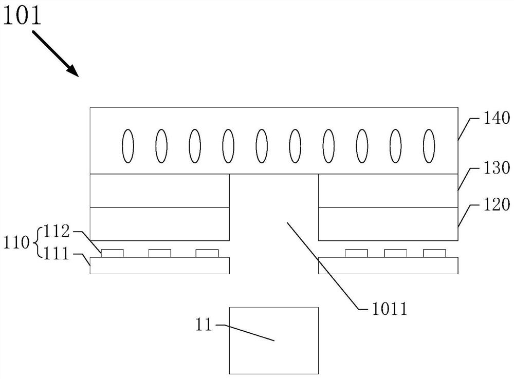
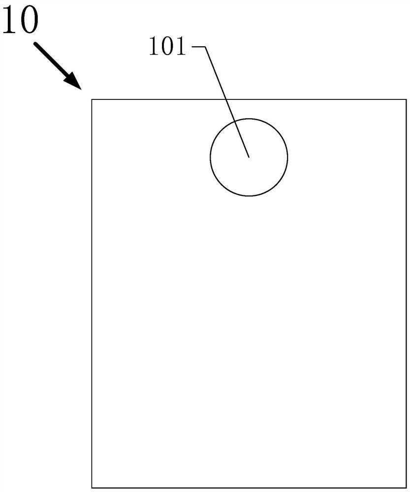
[0035] Such as figure 1 with figure 2 As shown, in this embodiment, the display panel 10 of the present invention includes an imaging area 101 , and the display panel 10 also includes an LED lamp panel 110 , a light control layer 120 , a diffusion layer 130 and a liquid crystal structure layer 140 .

[0036] The LED lamp board 110 includes a base plate 111 and a number of LED lamp beads 112. The LED lamp beads 112 are arranged in an array on the base board 111, which may be a monochrome chip. At this time, the LED lamp board 110 is a monochrome As a light source, the LED lamp bead 112 may also be a three-color chip, and at this time, the LED lamp board 110 is a color light source.

[0037] When the display panel 10 turns on the camera function or camera function, the LED lamp bead 112 on the LED lamp board 110 is turned off; The LED lamp bead 112 is turned on, so that the camera area 101 can display images normally, achieving a full-screen effect.

[0038] In order to ensu...

Embodiment 2

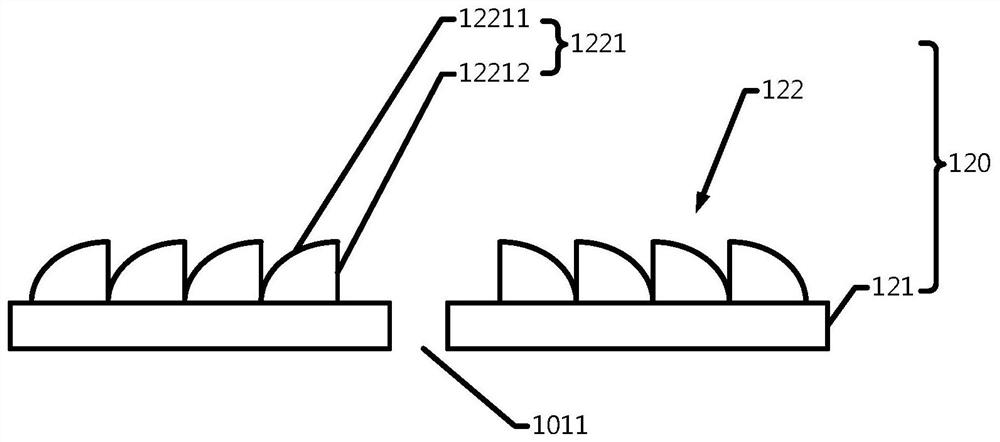
[0049] In this embodiment, the display panel 20 of the present invention is substantially similar to that in Embodiment 1, the difference lies in that, as Figure 4 As shown, the refraction structure 122 in this embodiment includes a first refraction structure 122 and a second refraction structure 123 .

[0050] The first refraction structure 122 is arranged on the side of the body film layer 121 away from the LED light board 110, and includes a plurality of first refraction units 1221 arranged in an array, and the first refraction unit 1221 includes a first arc shape surface 12211 and a first vertical surface 12212.

[0051] The first arc-shaped surface 12211 extends from the first surface 1211 toward the diffusion layer 130 and the groove 1011, and the two ends of the first vertical surface 12212 are connected to the first arc-shaped surface 12211 and the first surface 1211.

[0052] The second refraction structure 123 is disposed on the second surface 1212 of the body fil...


PUM

PropertyMeasurementUnit
diameteraaaaaaaaaa

Abstract

The invention discloses a display panel and a display device, comprising an imaging area and a main display area surrounding the imaging area, including an LED lamp board in the imaging area; a light control layer arranged on the LED lamp board; a diffusion layer arranged on the LED lamp board. on the light control layer; the liquid crystal structure layer is arranged on the diffusion layer; the groove extends from the LED light board to the surface of the liquid crystal structure layer close to the diffusion layer. The beneficial effect of the present invention is that the display panel and the display device of the present invention, by setting a camera hole in the camera area, light can enter the camera through the camera hole, ensuring the amount of light required for the camera to take pictures, and at the same time, LED light boards are set around the camera, The camera area can display images when the camera is turned off. At the same time, a layer of light control layer is set on the LED light board. The light on both sides of the groove is refracted into the groove through the mirror-symmetrical refraction structure of the Cosmos groove on the light control layer. When the camera is not working, the display panel above the groove can display images normally, realizing a real full screen.

Description

technical field [0001] The invention relates to the display field, in particular to a display panel and a display device. Background technique [0002] With the continuous development and advancement of low temperature polysilicon technology LTPS (Low Temperature Poly-silicon) small-size display technology, full-screen technology has become the mainstream technology in the mobile phone market. And blind hole full-screen technology emerges in an endless stream, and its ever-increasing screen-to-body ratio of mobile phones continues to push the full-screen technology to the extreme. However, the above three technologies all need to dig holes or special-shaped processing in some areas, and need to expose the area where the camera is located for taking pictures, so it is impossible to achieve a true full-screen display. For this reason, people are also trying to further increase the screen-to-body ratio by displaying the camera area, but how to achieve a perfect combination of ...

Claims


Application Information

Patent Timeline
Patent Type & Authority Patents(China)
IPC IPC(8): G02F1/1333G02F1/13357G02F1/1335
CPCG02F1/1333G02F1/1335G02F1/1336
Inventor 杨勇
Owner WUHAN CHINA STAR OPTOELECTRONICS TECH CO LTD
Why Eureka
Try Eureka