Optical scanning lens and scanning equipment
An optical scanning and lens technology, applied in the field of optical lenses, can solve the problem of difficulty in taking into account the volume and scanning effect, and achieve the effect of high imaging quality, stable imaging quality, and ensuring scanning effect.
- Summary
- Abstract
- Description
- Claims
- Application Information
AI Technical Summary
Problems solved by technology
Method used
Image

Examples
Embodiment 1
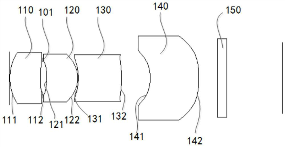
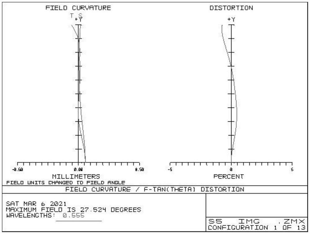
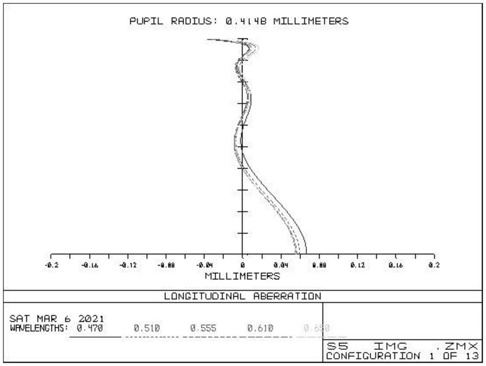
[0088] see Figure 1 to Figure 3 , figure 1 It shows a schematic diagram of an optical scanning lens according to Embodiment 1 of the present invention, figure 2 From left to right are the astigmatism and distortion curves of an optical scanning lens according to Embodiment 1 of the present invention, image 3 It is a spherical aberration curve diagram of an optical scanning lens according to Embodiment 1 of the present invention.
[0089] The present invention provides an optical scanning lens, which sequentially includes a first lens 110, a diaphragm 101, a second lens 120, a third lens 130, and a fourth lens 140 along the optical axis from the object side to the image side. Each of the four lenses 140 has an object-side surface facing the object side and an image-side surface facing the image side; the optical scanning lens also includes an imaging surface on the image side for imaging the subject.
[0090] In the optical scanning lens, the aperture is located between t...
Embodiment 2
[0104] see Figure 4 to Figure 6 , Figure 4 It shows a schematic diagram of an optical scanning lens according to Embodiment 2 of the present invention, Figure 5 From left to right are the astigmatism and distortion curves of an optical scanning lens according to Embodiment 2 of the present invention, Image 6 It is a spherical aberration curve diagram of an optical scanning lens according to Embodiment 2 of the present invention.
[0105] The present invention provides an optical scanning lens, which sequentially includes a first lens 210, a diaphragm 201, a second lens 220, a third lens 230, and a fourth lens 240 along the optical axis from the object side to the image side. Each of the four lenses 240 has an object-side surface facing the object side and an image-side surface facing the image side; the optical scanning lens also includes an imaging surface on the image side for imaging the subject.
[0106] In the optical scanning lens, the aperture 201 is located betw...
Embodiment 3
[0119] see Figure 7 to Figure 9 , Figure 7 shows a schematic diagram of an optical scanning lens according to Embodiment 3 of the present invention, Figure 8 From left to right are the astigmatism and distortion curves of an optical scanning lens according to Embodiment 3 of the present invention, Figure 9 It is a spherical aberration curve diagram of an optical scanning lens according to Embodiment 3 of the present invention.
[0120] The present invention provides an optical scanning lens, which sequentially includes a first lens 310, a diaphragm 301, a second lens 320, a third lens 330, and a fourth lens 340 along the optical axis from the object side to the image side. Each of the four lenses 340 has an object-side surface facing the object side and an image-side surface facing the image side; the optical scanning lens also includes an imaging surface on the image side for imaging the subject.
[0121] In the optical scanning lens, the aperture 301 is located betwee...
PUM
 Abstract
Description
Claims
Application Information
 - Generate Ideas
- Intellectual Property
- Life Sciences
- Materials
- Tech Scout
- Unparalleled Data Quality
- Higher Quality Content
- 60% Fewer Hallucinations
Browse by: Latest US Patents, China's latest patents, Technical Efficacy Thesaurus, Application Domain, Technology Topic, Popular Technical Reports.
© 2025 PatSnap. All rights reserved.Legal|Privacy policy|Modern Slavery Act Transparency Statement|Sitemap|About US| Contact US: help@patsnap.com