Imaging method, device and electronic equipment based on array camera
An array camera and imaging method technology, applied in television, electrical components, image communication, etc., can solve problems such as poor imaging quality in dark light, achieve the effect of improving imaging quality and solving poor imaging quality in dark light
- Summary
- Abstract
- Description
- Claims
- Application Information
AI Technical Summary
Problems solved by technology
Method used
Image


Examples
Embodiment 1
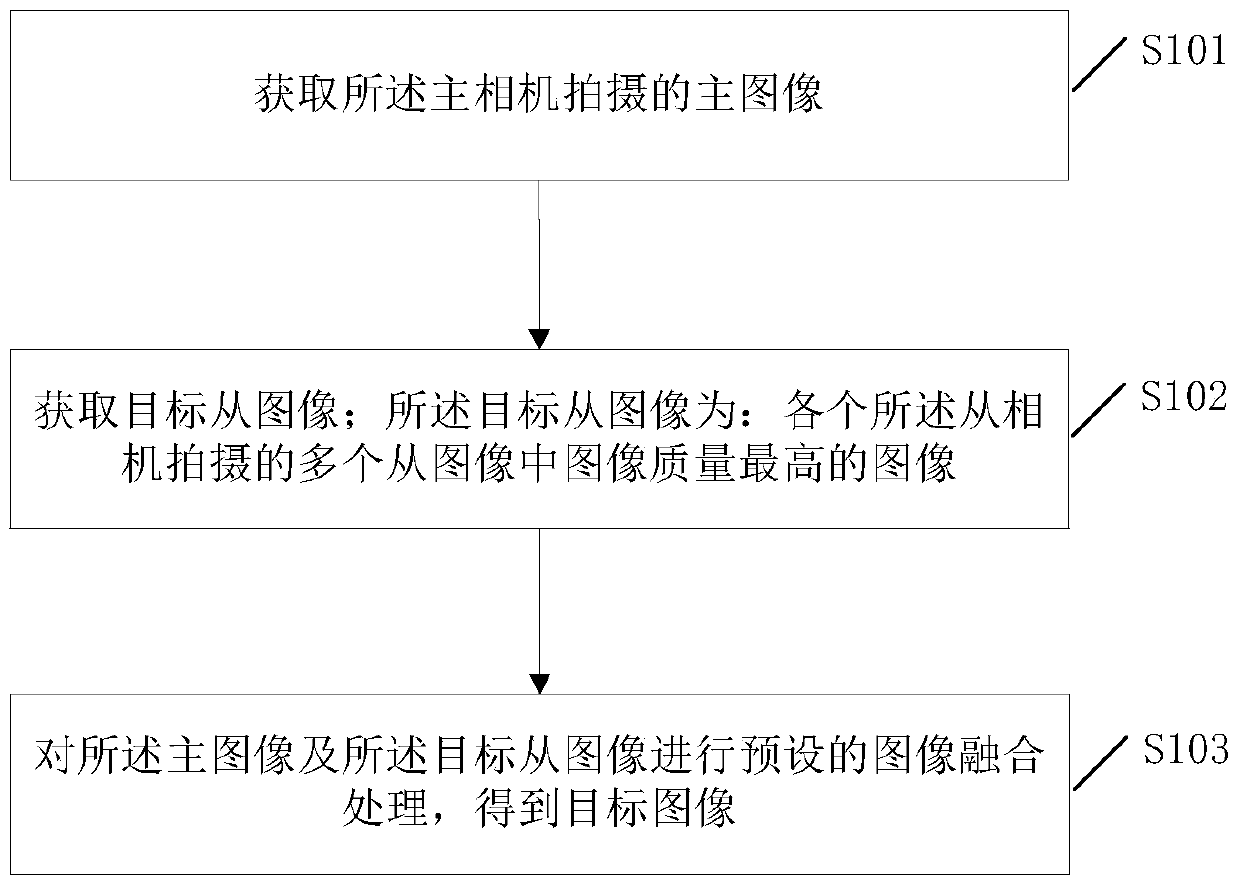
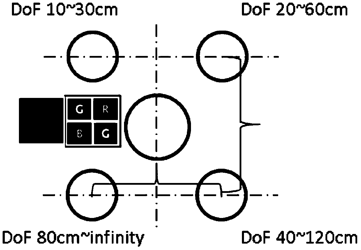
[0069] refer to figure 1 , figure 1 It is a flowchart of Embodiment 1 of an imaging method based on an array camera provided by the present application. The array camera includes a main camera and a predetermined number of slave cameras, each of the slave cameras adopts a large aperture, and each of the slave cameras The depth of field overlaps sequentially, and the method can be applied to electronic devices such as smart phones, tablet computers, and ordinary cameras, such as figure 1 As shown, the method may include the following steps:
[0070] S101: Acquire a main image captured by the main camera.
[0071] S102: Acquire a target secondary image; the target secondary image is: an image with the highest image quality among multiple secondary images captured by each of the secondary cameras.
[0072] S103: Perform preset image fusion processing on the master image and the target slave image to obtain a target image.
[0073] In order to solve the problem of poor dark li...
Embodiment 2
[0083] refer to image 3 , image 3 It is a flow chart of Embodiment 2 of an imaging method based on an array camera provided in this application. In this embodiment, the step S103 can be specifically implemented through the following steps:
[0084] S301: Obtain grayscale images corresponding to the master image and the target slave image respectively, to obtain a master camera grayscale image and a slave camera grayscale image;
[0085] S302: Obtain color information of the main image;
[0086] S303: Fusing the master camera grayscale image and the slave camera grayscale image to obtain a target grayscale image;
[0087] S304: Fuse the target grayscale image and the color information to obtain a target image.
[0088] This embodiment specifically describes the image fusion process of the master image and the target slave image.
[0089] First extract the color information of the main image, and perform grayscale processing on the main image and the target secondary image...
Embodiment 3
[0094] refer to Figure 4 , Figure 4 It is a flow chart of Embodiment 3 of an array camera-based imaging method provided by this application. In this embodiment, the method further includes the following preprocessing process:
[0095] S401: Obtain a first reference secondary image and a second reference secondary image; the first reference secondary image and the second reference secondary image are: two images with the highest image quality among multiple secondary images captured by each secondary camera image;
[0096] S402: Based on the principle of stereo vision, calculate a reference focus distance by using the first reference slave image and the second reference slave image;
[0097] S403: Search in a preset search field centered on the reference focus distance to obtain a target focus distance; the target focus distance is: a focus distance value corresponding to the highest image quality of the main camera in the preset search field ;
[0098] S404: Based on the...
PUM
 Abstract
Description
Claims
Application Information
 - R&D
- Intellectual Property
- Life Sciences
- Materials
- Tech Scout
- Unparalleled Data Quality
- Higher Quality Content
- 60% Fewer Hallucinations
Browse by: Latest US Patents, China's latest patents, Technical Efficacy Thesaurus, Application Domain, Technology Topic, Popular Technical Reports.
© 2025 PatSnap. All rights reserved.Legal|Privacy policy|Modern Slavery Act Transparency Statement|Sitemap|About US| Contact US: help@patsnap.com