
Radio frequency power amplifier for Internet of Vehicles communication

A radio frequency power and amplifier technology, applied in the field of radio frequency power amplifier chip circuits, can solve the problems of increasing circuit complexity, limiting the gain of a single power amplifier tube, and increasing the deterioration of insertion loss, so as to improve the impedance matching between stages, improve the gain and efficiency, The effect of improving circuit stability

Pending Publication Date: 2020-02-14
重庆桴之科科技发展有限公司 +1
View PDF0 Cites 13 Cited by
  • Summary
  • Abstract
  • Description
  • Claims
  • Application Information

AI Technical Summary

Problems solved by technology

[0003] (1) The power amplifier efficiency is limited under high back-off power, and the power consumption is high: when the traditional AB class power amplifier realizes peak-to-average ratio signal amplification, the efficiency is low under high back-off power, so the power consumption is large
[0004] (2) The power gain is limited, and the insertion loss is greatly deteriorated: the 5.9 GHz frequency band is often implemented by a semiconductor process with a lower cost and a lower characteristic frequency, which limits the single-tube gain of the power amplifier, and with the increase of the frequency band , the parasitic parameters of the transistor become larger, and the parasitic loss of the circuit deteriorates greatly, which affects the performance of the circuit;
[0005] (3) Limitation of using lumped parameter circuit design: When designing traditional lumped parameter RLC matching circuits in the 5.9 GHz frequency band, it is still necessary to use devices with large chip areas such as inductors and capacitors, and due to the increased substrate loss, the inductance Q The value is low, so it brings limitations to the circuit design
[0007] (1) When the traditional Doherty single-ended power amplifier realizes the 5.9 GHz frequency band circuit design, due to the influence of parasitic parameters, the fallback efficiency index is often poor;
[0008] (2) When the traditional Doherty single-ended power amplifier realizes the 5.9 GHz frequency band circuit design, it often uses the AB class drive amplifier to drive the Doherty amplifier. The good load-pull effect under the high back-off of the main circuit and the auxiliary circuit of the amplifier leads to a decrease in the back-off efficiency and a deterioration of the linearity index
[0009] In addition, the use of depletion-type field effect transistors often requires additional negative voltage supply, which will also increase the complexity of the circuit

Method used


Image

  • Radio frequency power amplifier for Internet of Vehicles communication
  • Radio frequency power amplifier for Internet of Vehicles communication

Examples


Embodiment Construction

[0026] Exemplary embodiments of the present invention will now be described in detail with reference to the accompanying drawings. It should be understood that the implementations shown and described in the drawings are only exemplary, intended to explain the principle and spirit of the present invention, rather than limit the scope of the present invention.

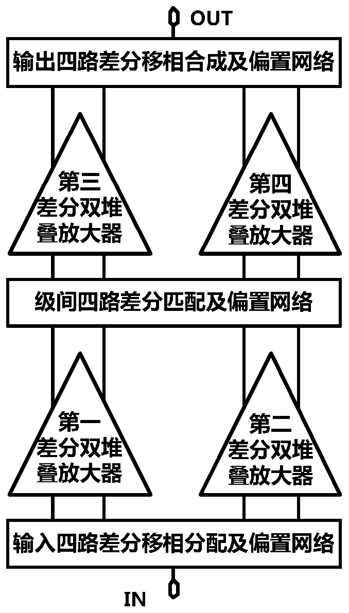
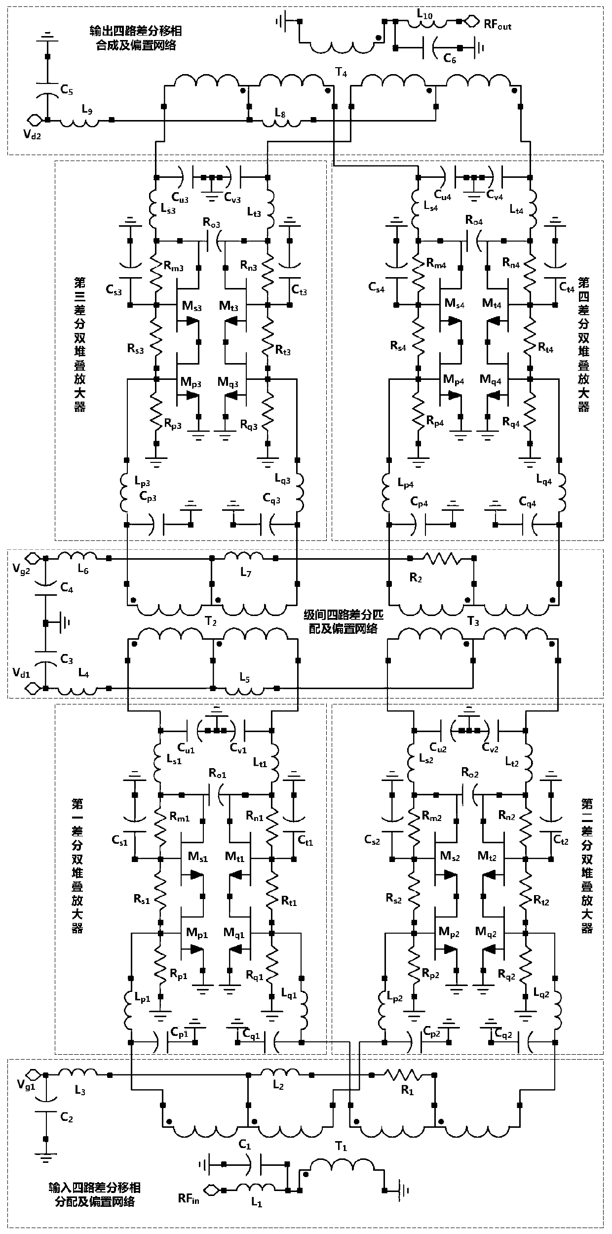
[0027] An embodiment of the present invention provides a radio frequency power amplifier for Internet of Vehicles communication, including input four-way differential phase-shift distribution and bias network, a first differential double stack amplifier, a second differential double stack amplifier, and a third differential double stack amplifier , the fourth differential double stack amplifier, four-way differential matching and bias network between stages, and four-way differential phase-shift synthesis and bias network for output.

[0028] Such as figure 1 As shown, the input terminal of the four-way differential pha...


PUM


Abstract

The invention discloses a radio frequency power amplifier for Internet of Vehicles communication. The radio frequency power amplifier comprises an input four-path differential phase shift distributionand bias network, a first differential double-stack amplifier, a second differential double-stack amplifier, a third differential double-stack amplifier, a fourth differential double-stack amplifier,an inter-stage four-path differential matching and bias network and an output four-path differential phase shift synthesis and bias network. The core architecture of the invention adopts the characteristics of high power and high gain of a double-stack amplification network formed by field effect transistors in a radio frequency microwave band; and meanwhile, the good parasitic parameter inhibition of the differential amplifier in a microwave frequency band is combined with the good power back-off efficiency characteristic of the two-stage Doherty driving amplification structure, so that thewhole power amplifier obtains good high gain, high back-off efficiency and high power output capability.

Description

technical field [0001] The invention relates to field effect transistor radio frequency power amplifiers and integrated circuits, in particular to a radio frequency power amplifier chip circuit for vehicle networking communication for a transmitting module of a cellular technology-based vehicle networking communication (C-V2X) application. Background technique [0002] With the rapid development of 5G wireless communication systems and radio frequency circuits, the Internet of Vehicles communication based on cellular technology in the 5.9GHz frequency band also has unprecedented application space, and its radio frequency front-end transceiver circuits are also developing in the direction of high performance, high integration, and low power consumption. Therefore, the car networking communication market urgently needs the radio frequency power amplifier of the transmitter to have high linear output power and efficiency, reduce heat dissipation, and improve circuit stability, a...

Claims


Application Information

Patent Timeline
Patent Type & Authority Applications(China)
IPC IPC(8): H03F3/193H03F3/195H03F3/213H03F3/45H03F3/68H03G3/30H03F1/02H03F1/56
CPCH03F1/0211H03F1/0288H03F1/565H03F3/193H03F3/195H03F3/213H03F3/45179H03F3/45475H03F3/68H03F2200/451H03G3/3036
Inventor 刘林盛邬海峰李辉梁尚春赵元林
Owner 重庆桴之科科技发展有限公司
Learn More