Eureka AIR delivers breakthrough ideas for toughest innovation challenges, trusted by R&D personnel around the world.

Limestone powder calcining furnace

A technology of limestone powder and calciner, applied in the field of limestone powder calciner, can solve the problems of low discharge efficiency, large floor space, waste of resources, etc., and achieves the advantages of slowing down the unloading speed, effectively utilizing waste heat, and high discharging efficiency. Effect

Inactive Publication Date: 2020-02-14
河南越尔环保科技有限公司
View PDF0 Cites 5 Cited by
  • Summary
  • Abstract
  • Description
  • Claims
  • Application Information

AI Technical Summary

Problems solved by technology

[0002] In the process of mine processing, a large amount of limestone powder will be produced. Limestone powder is piled up in the mine as mine waste, which occupies a large area, causes waste of resources, and pollutes the environment. Calciner can be used to calcine and reuse limestone powder. The existing calcination furnace has a fast feeding speed, and only one long stirring shaft is used for stirring. The stirring shaft needs to be made of special heat-resistant steel. The wall sticking phenomenon occurs, the unloading efficiency is low, and the high-temperature harmful exhaust gas is directly discharged into the environment, polluting the environment; therefore, it is urgent to design a low-cost, slow down the feeding speed, and the limestone powder is calcined thoroughly, avoiding the wall sticking phenomenon, unloading Limestone powder calcination furnace with high material efficiency, effective use of waste heat in tail gas, treatment of tail gas and then discharge to the environment, reduction of tail gas pollution to the environment, energy saving and environmental protection

Method used


Image

  • Limestone powder calcining furnace
  • Limestone powder calcining furnace
  • Limestone powder calcining furnace

Examples


Embodiment 1

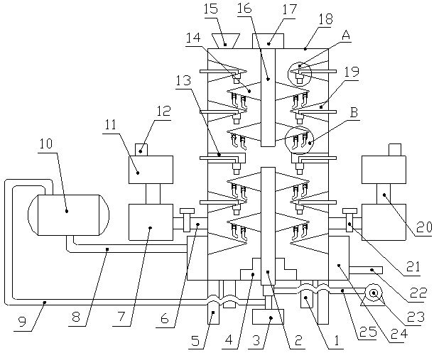
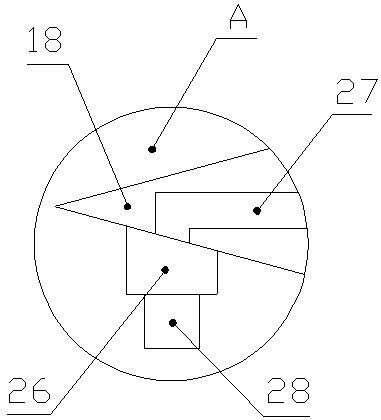
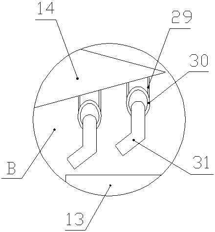
[0026] like Figure 1-4As shown, a limestone powder calciner includes a furnace body 18, the lower surface of the furnace body 18 is fixedly connected with a support leg 5, and the left side of the upper surface of the described furnace body 18 is fixedly connected with a feed hopper 15, so The middle part of the upper surface of the furnace body 18 is fixed with a motor B17, the output shaft of the motor B17 is connected to the stirring shaft B16, and the lower end of the stirring shaft B16 penetrates the upper side wall of the furnace body 18 and extends into the furnace body 18. In the upper part, a motor A3 is arranged below the furnace body 18, the output shaft of the motor A3 is connected to a stirring shaft A2, and the upper end of the stirring shaft A2 penetrates the lower side wall of the furnace body 18 and extends into the furnace body 18 The lower part, the stirring shaft A2 and the stirring shaft B16 are fixedly connected with stirring blades 14, the middle part o...


PUM


Abstract

The invention discloses a limestone powder calcining furnace which comprises a furnace body, wherein the left side and the middle of the upper surface of the furnace body are connected with a feedinghopper and a motor B respectively; a motor A is arranged below the furnace body; output shafts of the motor A and the motor B are respectively connected with a stirring shaft A and a stirring shaft B;stirring blades are connected to the stirring shaft A and the stirring shaft B; high-temperature belts are connected to the middle of the inner side wall of the furnace body; the upper and lower parts of the inner side wall of the furnace body are connected with guide plates; the lower surfaces of the guide plates and the high-temperature belts are connected with material blowing devices; the lower surfaces of the stirring blades are connected with poking devices; the outer side of the stirring shaft A is connected with a discharge tower through a bearing; the outer side of the lower part ofthe furnace body is sleeved by a cooling sleeve; the lower part of the right side of the cooling sleeve is connected with a liquid inlet pipe; the upper part of the left side of the cooling sleeve isconnected with the inlet end of a steam drum through a liquid outlet pipe; the outlet end of the steam drum is connected with the stirring shaft A through a steam pipe; and the left side and the rightside of the lower surface of the furnace body are connected with discharge tubes. The limestone powder calcining furnace has the advantages of thorough calcination, wall adhesion prevention, high discharge efficiency, energy conservation and environment protection.

Description

technical field [0001] The invention belongs to the technical field of calcination equipment, in particular to a limestone powder calcination furnace. Background technique [0002] In the process of mine processing, a large amount of limestone powder will be produced. Limestone powder is piled up in the mine as mine waste, which occupies a large area, causes waste of resources, and pollutes the environment. Calciner can be used to calcine and reuse limestone powder. The existing calcination furnace has a fast feeding speed, and only one long stirring shaft is used for stirring. The stirring shaft needs to be made of special heat-resistant steel. The wall sticking phenomenon occurs, the unloading efficiency is low, and the high-temperature harmful exhaust gas is directly discharged into the environment, polluting the environment; therefore, it is urgent to design a low-cost, slow down the feeding speed, and the limestone powder is calcined thoroughly, avoiding the wall sticki...

Claims


Application Information

Patent Timeline
IPC IPC(8): C04B2/10
CPCC04B2/10
Inventor 杨西建苏国平
Owner 河南越尔环保科技有限公司
Why Eureka
Eureka Blog
Learn More