Serialized perfusion type microfluidic device
A microfluidic device and perfusion technology, applied in the field of biomedicine, can solve problems such as difficult to achieve cryoprotectant treatment, and achieve the effect of avoiding the accumulation effect of osmotic pressure difference and reducing osmotic damage
- Summary
- Abstract
- Description
- Claims
- Application Information
AI Technical Summary
Problems solved by technology
Method used
Image

Examples
Embodiment 1
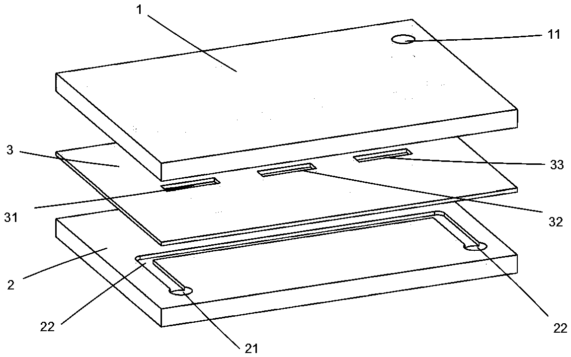
[0040] see figure 1 with figure 2 , a serialized perfusion microfluidic device comprising a plate-shaped perfusion-side body 1 , a plate-shaped middle layer body 3 and a plate-shaped cell-side body 2 arranged in sequence from top to bottom.
[0041] The materials of the body 1 on the perfusion side, the body 2 on the cell side and the body 3 on the middle layer are the same, all being polymethyl methacrylate (PMMA). The thickness of the perfusion side body 1 is 10 mm, the thickness of the cell side body 2 is 5 mm; the thickness of the middle layer body 3 is 0.1 mm.
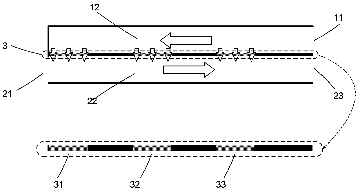
[0042] The perfusion side body 1 is provided with a perfusion side inlet 11, and the inner surface of the perfusion side body 1 corresponding to the three membrane windows on the middle layer body 3 is provided with a perfusion side flow channel 12. The total length of the flow channel 12 is 300mm, width 1mm, and depth 0.5mm, one end of the perfusion side channel 12 is connected to the perfusion side inlet 11;
...
Embodiment 2
[0047] Add cryoprotectant to stem cell suspension.
[0048] The commonly used cryoprotectant for stem cell cryopreservation is DMSO with a concentration of 10%. To add DMSO to the cell suspension to this target concentration, the following setup was used: a 20% DMSO solution was used as the perfusate, and the initial concentration of DMSO in the stem cell suspension was 0%. The specific form of setting the serialized perfusion microfluidic device is as described in Example 1. During the treatment process, the flow rate of the cell suspension at the cell side inlet 21 is 1ml / min, which is injected from the cell side inlet 21; the perfusate at the perfusion side inlet 11 The flow rate is the same as 1ml / min, which is injected from the inlet 11 on the perfusion side; the perfusate of the injection device flows into the stem cell suspension through the first membrane window 31, the second membrane window 32, and the third membrane window 32, and finally flows through the cell side...
Embodiment 3
[0056] Removal of cryoprotectants from stem cell suspensions
[0057] The device of the present invention can be used to remove the cryoprotectant in the stem cells with physiological saline as the perfusate. Pass the cell suspension containing the cryoprotectant through the inlet 21 of the cell fluid side, and set the inlet flow rate to 0.5ml / min; feed the perfusate into the perfusate inlet 11, and set the inlet flow rate to 5ml / min; In 23 places, the cell suspension with a fixed dilution ratio can be obtained, and the removal rate of the cryoprotectant in the cells is above 90%.
[0058] Below in conjunction with accompanying drawing, the principle of present embodiment 3 is described in further detail:
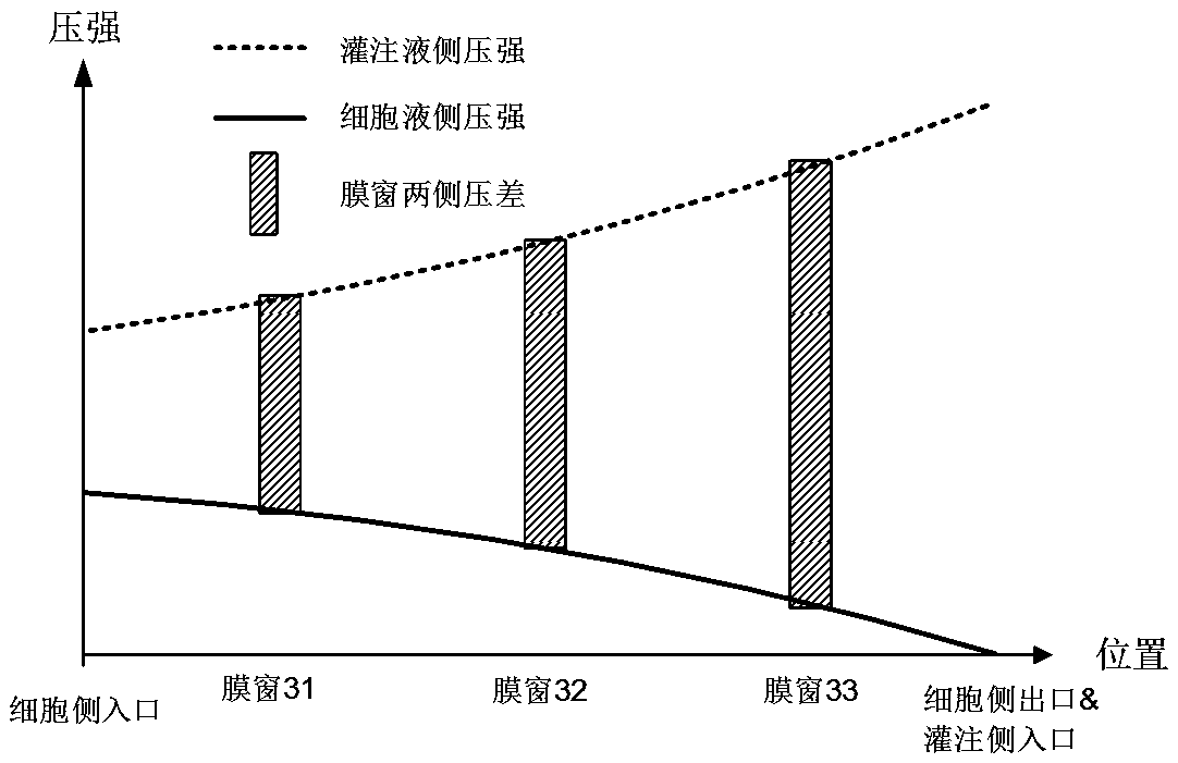
[0059] join Figure 7 In embodiment 3, the reverse flow of flow channels on both sides of the device forms transmembrane pressures that increase sequentially on both sides of the three membrane windows, and the principle is the same as in embodiment 2.
[0060] see Fig...
PUM
| Property | Measurement | Unit |
|---|---|---|
| width | aaaaa | aaaaa |
| length | aaaaa | aaaaa |
| thickness | aaaaa | aaaaa |
Abstract
Description
Claims
Application Information
 - Generate Ideas
- Intellectual Property
- Life Sciences
- Materials
- Tech Scout
- Unparalleled Data Quality
- Higher Quality Content
- 60% Fewer Hallucinations
Browse by: Latest US Patents, China's latest patents, Technical Efficacy Thesaurus, Application Domain, Technology Topic, Popular Technical Reports.
© 2025 PatSnap. All rights reserved.Legal|Privacy policy|Modern Slavery Act Transparency Statement|Sitemap|About US| Contact US: help@patsnap.com