
Deep hole grinding and cleaning device

A cleaning device and deep hole technology, applied in the direction of grinding drive device, cleaning method and tools, cleaning method using tools, etc., can solve the problem that deep holes cannot be ground and cleaned, and achieve simple structure, good cleaning effect, adaptable effect

Pending Publication Date: 2020-01-21
ANQING CSSC DIESEL ENGINE
View PDF1 Cites 0 Cited by
  • Summary
  • Abstract
  • Description
  • Claims
  • Application Information

AI Technical Summary

Problems solved by technology

[0005] The technical problem to be solved by the present invention is: how to solve the problem that deep holes cannot be polished and cleaned

Method used


Image

  • Deep hole grinding and cleaning device
  • Deep hole grinding and cleaning device
  • Deep hole grinding and cleaning device

Examples


Embodiment 1

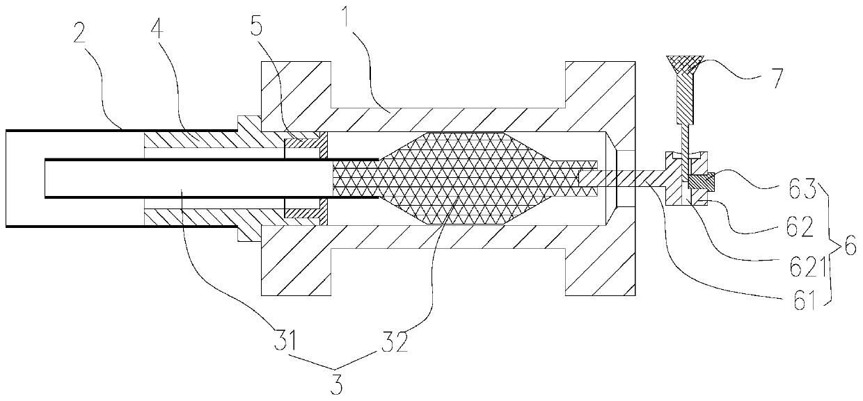
[0034] like figure 1 As shown, in the present embodiment, the deep hole grinding and cleaning device includes a power rotating part, a support body 1, a hand-held part 2, a grinding part or a cleaning part, and the support body 1 is fixedly connected with one end of the hand-held part 2, and the inside of the support body 1 It is a cavity, one end of the power rotating part is installed in the cavity, and the other end drives and connects the grinding or cleaning part. When grinding or cleaning, the grinding or cleaning part rotates with the length of the grinding or cleaning part as the radius.

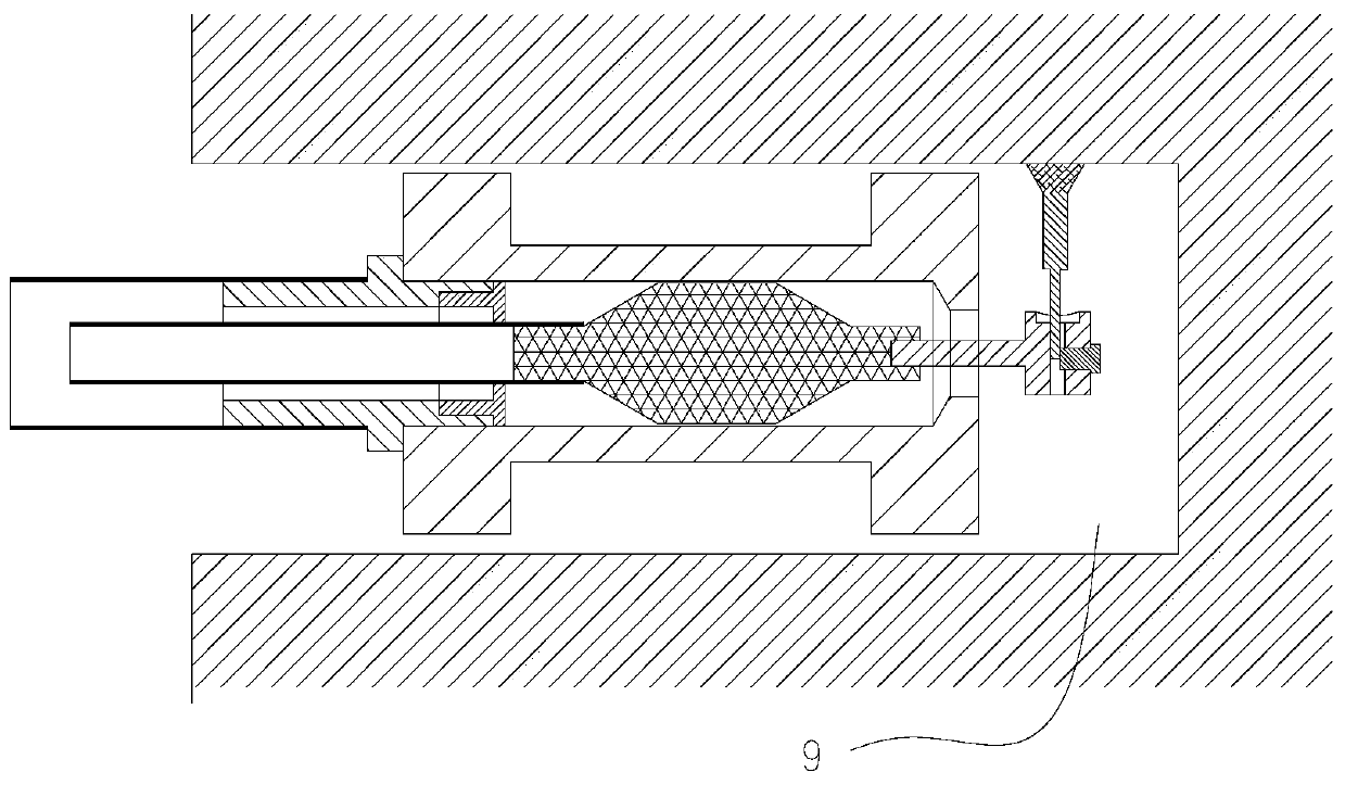
[0035] The stent body 1 is a hollow cylindrical structure, and the outer diameter of the stent body 1 is smaller than the inner diameter of the deep hole 9. Specifically, the outer diameter of the stent body is generally less than about 3mm of the cleaning hole, which can ensure the entire device to a certain extent. The stability in the deep hole 9 can ensure that the movement of th...

Embodiment 2

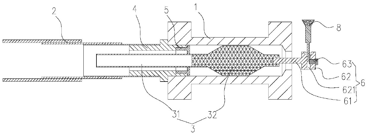
[0045] like figure 2 As shown, the handle 2 is a plurality of telescopically connected hollow steel pipes. The outer diameters of the multiple hollow steel pipes increase sequentially. connected to the outside. The means to achieve shrinkage can be: setting a slider in one of the two relatively interacting hollow steel pipes, and setting a chute in the other, so that relative sliding can be achieved, and expansion and contraction can be achieved; other structures that can achieve expansion and contraction can also be used. can be referenced.

[0046] The telescopic structure realized by a plurality of hollow steel pipe parts meets the needs of different deep holes 9 and has stronger adaptability.

[0047] It should be noted that: if figure 1 , 2 As shown, the cleaning member 7 in the first embodiment and the second embodiment is a brush. One end of the brush is a round rod for easy insertion into the through hole, and the other end is a cleaning head. The grinding piece...


PUM


Abstract

The invention discloses a deep hole grinding and cleaning device. The deep hole grinding and cleaning device comprises a power rotating part, a support body, a handheld part and a grinding part or a cleaning part, wherein the support body is fixedly connected with one end of the handheld part; a cavity is formed in the support body; one end of the power rotating part is mounted in the cavity, andthe other end of the power rotating part is in driving connection with the grinding part or the cleaning part. During grinding or cleaning, the grinding part or the cleaning part rotates with the length of the grinding part or the cleaning part as the radius. The deep hole grinding and cleaning device has the beneficial effects that a power source is provided through the power rotating part, rotating movement is achieved, then the grinding part or the cleaning part is driven to do circular movement, and the inner wall of a deep hole is ground or cleaned; and the grinding part or the cleaning part can be detached, grinding or / and cleaning can be conducted according to needs, the defects of residual molding sand, paint and the like on the side wall of the deep hole in all castings are effectively ground and cleaned, time and labor are saved, the cleaning effect is good, and the structure is simple.

Description

technical field [0001] The invention relates to a grinding and cleaning device, in particular to a deep hole grinding and cleaning device. Background technique [0002] Due to the different shape and structure of the products produced by casting, some of them have some deep holes, which cannot be deeply polished and cleaned by ordinary grinding and cleaning tools; [0003] At present, there are also some tools used for grinding. For example, the application number is 201510726080.3, which discloses a grinding machine for grinding deeper holes, including a large tube, a small tube, an adjustment groove, an axis, an adjustment bolt, and a grinding head. The large tube is hollow. The small tube is inserted into the large tube, and the large tube is designed with an adjusting groove, the axis is fixed on the small tube, the adjusting screw of the large tube corresponding to the axis is fixed with an adjusting bolt, and the grinding head is fixed on the tip of the small tube. Th...

Claims


Application Information

Patent Timeline
IPC IPC(8): B24B23/02B24B47/14B08B1/04
CPCB24B23/02B24B47/14B08B1/32B08B1/12
Inventor 陆程翔苏书龙孙自红谢洪祥陈龙丁小胜
Owner ANQING CSSC DIESEL ENGINE
Learn More