Honeycomb amplification type fiber push-out device and working method thereof

A push-out, honeycomb-type technology, applied in measurement devices, piezoelectric/electrostrictive or magnetostrictive motors, instruments, etc., can solve the problems of easy instability, low precision, fiber damage, etc. Inertia effect, large output force and displacement, uniform force distribution effect

Pending Publication Date: 2020-01-17
NANJING INST OF TECH
View PDF1 Cites 1 Cited by
  • Summary
  • Abstract
  • Description
  • Claims
  • Application Information

AI Technical Summary

Problems solved by technology

Early fiber ejection devices usually use servo motors to achieve ejection, which can satisfy large thrust and large stroke. The disadvantage is that the precision is not high, it is difficult to ensure the controllability of stepping motion, and it is easy to cause fiber damage.
[0004] The invention patent application (application number 201910061558.3) titled a fiber ejection device based on laminated piezoelectric ceramics and its working method discloses a fiber ejection device. Although piezoelectric elements are used, the laterally laminated Piezoelectric ceramic structure is prone to instability during pushing and is easily damaged by shear force
In addition, the push-out displacement it can produce is limited, and sometimes the single fiber cannot be completely pushed out, and the complete residual stress between the single fiber and the glass slide cannot be obtained
Secondly, the structure distribution of the horizontal push type causes the self-weight of the displacement output structure to produce lateral interference on the thimble, which affects the test results

Method used


Image

  • Honeycomb amplification type fiber push-out device and working method thereof
  • Honeycomb amplification type fiber push-out device and working method thereof
  • Honeycomb amplification type fiber push-out device and working method thereof

Examples


Embodiment Construction

[0036] The specific implementation manners of the present invention will be described below in conjunction with the accompanying drawings.

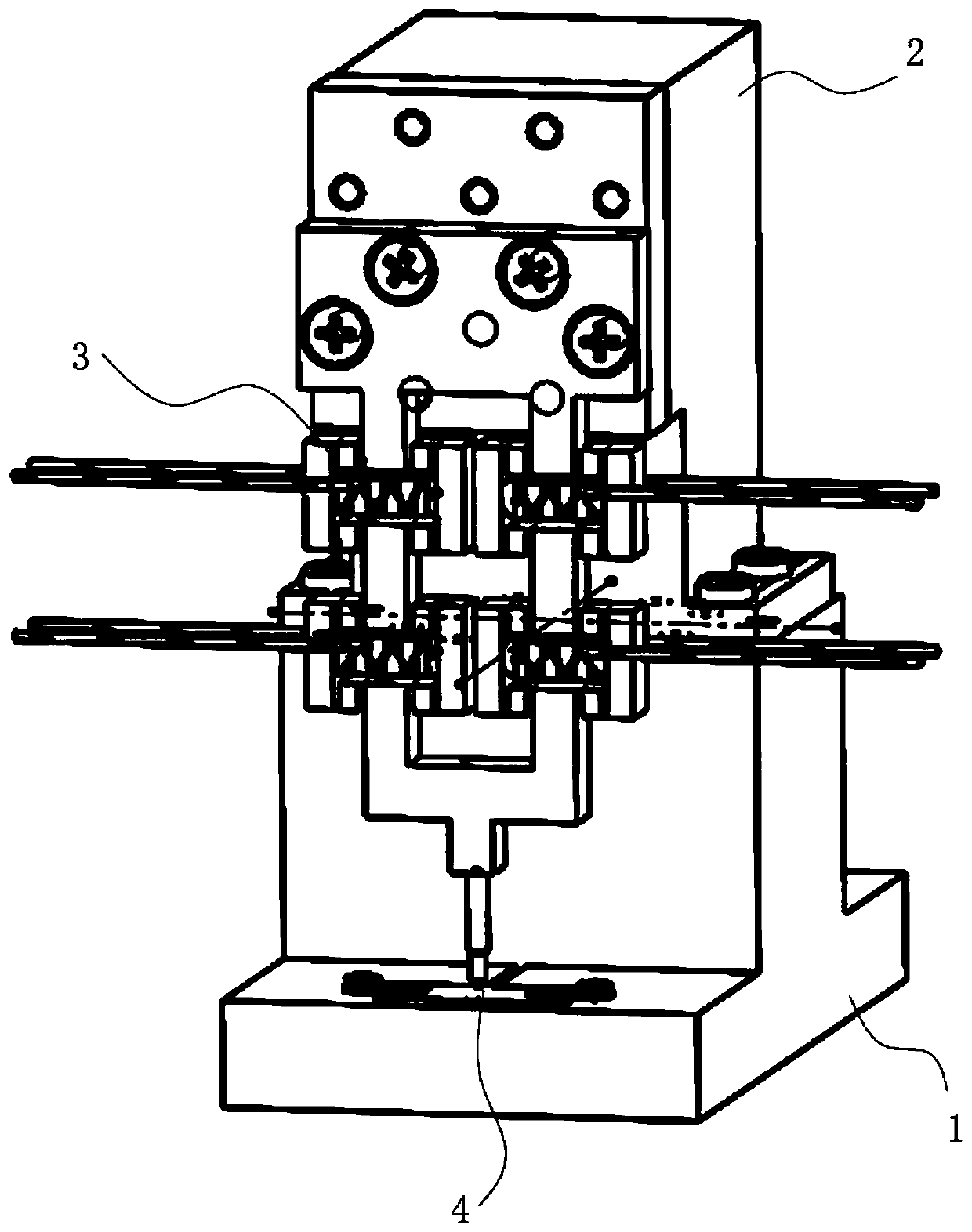
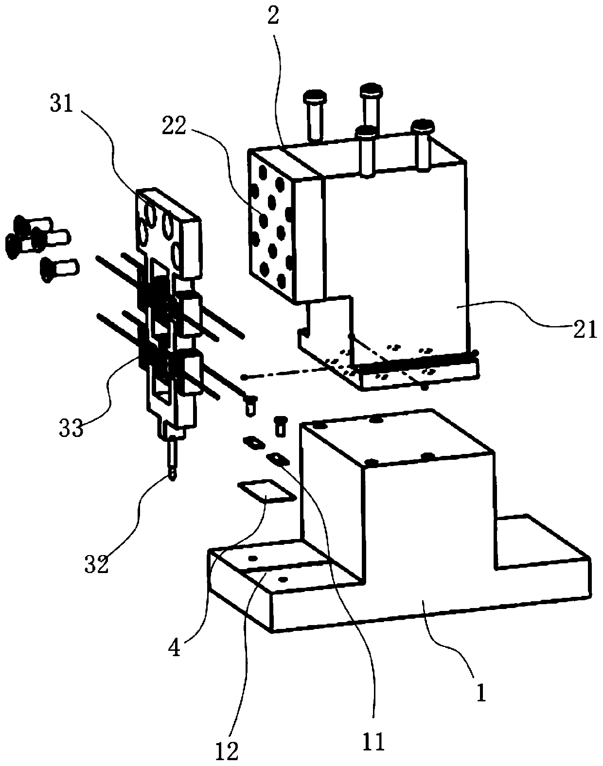
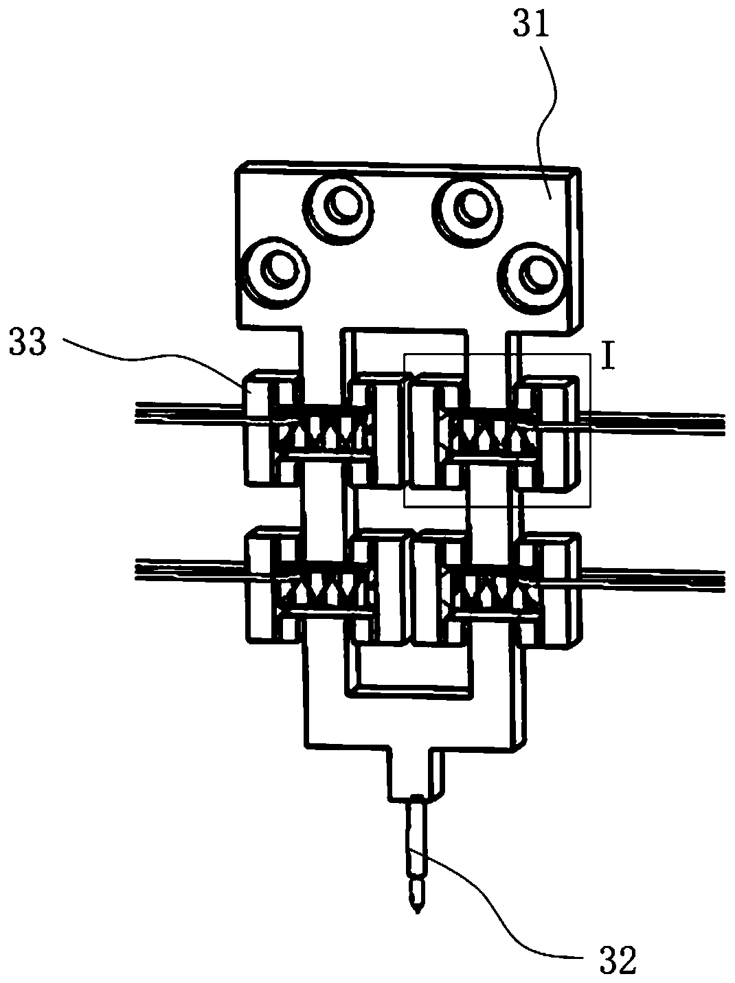
[0037] Such as figure 1 and 2 As shown, the present invention provides a honeycomb amplified fiber pushing device, which includes a workbench 1 , a manual adjustment micro-motion platform 2 and a honeycomb displacement output mechanism 3 .

[0038] The manual adjustment micro-motion platform 2 is fixed on the workbench 1, and the cellular displacement output mechanism 3 is fixed on the front side of the manual adjustment micro-motion platform 2. By adjusting the manual adjustment micro-motion platform 2, the cellular displacement output mechanism 3 is driven to move up and down.

[0039] Specifically, the workbench 1 has a front-rear symmetrical structure, the vertical section in the front-rear direction is an inverted T shape, and the surface of the middle part is higher than the surfaces of the front part and the rear part. The manual...


PUM


Abstract

The invention discloses a honeycomb amplification type fiber push-out device and a working method thereof. The device comprises a workbench, a manual adjustment micro-motion platform and a honeycomb type displacement output mechanism. The manual adjustment micro-motion platform is fixed to the workbench, and the honeycomb type displacement output mechanism is fixed to the front side of the manualadjustment micro-motion platform. The honeycomb type displacement output mechanism comprises a frame type honeycomb type amplification mechanism, an ejector pin and a plurality of groups of amplification assemblies; the amplification assemblies are arranged on the frame type honeycomb amplification mechanism; each amplification assembly comprises a bridge type amplification mechanism, a piezoelectric ceramic group, a piezoelectric ceramic positive electrode input wire and a piezoelectric ceramic negative electrode input wire; a detected fiber slide is fixed on the workbench and is positioned below the thimble; by inputting a signal into the piezoelectric ceramic group, the piezoelectric ceramic group extends and outputs displacement, the displacement is amplified by the bridge type amplification mechanism, and the ejector pin moves downwards along with the displacement to push out a single fiber of the fiber slide. The device has the advantages of simple structure, high response speed,high positioning precision and the like.

Description

technical field [0001] The invention belongs to the technical field of piezoelectric precision actuation, and relates to a fiber ejecting device, in particular to a honeycomb-amplified fiber ejecting device and a working method thereof. Background technique [0002] Piezoelectric actuation technology is an emerging technology that uses the inverse piezoelectric effect of piezoelectric materials to convert electrical energy into macroscopic motion. Because of its small size, high precision, fast response, self-locking when power is off, and no electromagnetic interference And other advantages, can meet the requirements of many high-tech fields. According to the different excitation modes during actuation, it can be divided into two types: resonance type and non-resonance type. The core component of the resonance type is a single piezoelectric ceramic sheet. The piezoelectric element is used to excite the resonance of the elastic body to obtain amplified deformation. The defo...

Claims


Application Information

Patent Timeline
IPC IPC(8): H02N2/02H02N2/04G01L1/00
CPCG01L1/00H02N2/02H02N2/043
Inventor 孙梦馨冯勇徐振钦
Owner NANJING INST OF TECH
Why Eureka
Try Eureka