
Negative-pressure polishing device and method for blind hole polishing for conductive workpieces

A polishing device and workpiece technology, which are applied to machine tools suitable for grinding workpiece edges, surface polishing machine tools, and workpiece supports, etc., can solve problems such as inability to polish.

Pending Publication Date: 2020-01-03
ZHEJIANG UNIV OF TECH
View PDF0 Cites 0 Cited by
  • Summary
  • Abstract
  • Description
  • Claims
  • Application Information

AI Technical Summary

Problems solved by technology

[0004] The purpose of the present invention is to solve the problem that the existing polishing method cannot polish the blind hole of the conductive workpiece printed by 3D printing technology, and proposes a negative pressure polishing device and method for polishing the blind hole of the conductive workpiece. Under the negative pressure polishing environment, the electromagnetic field controls the movement of the liquid metal abrasive grain flow to realize the automatic polishing of the blind hole of the workpiece to be processed. The blind hole of the workpiece to be processed is placed in a negative pressure state by pumping air, so that the liquid metal abrasive grain flow can be smoother. Entering the blind hole, during the polishing process, the electromagnetic field continuously acts on the liquid metal abrasive flow, and the liquid metal abrasive flow forms a good contact with the surface of the workpiece to be processed under the action of the electromagnetic field, and performs micro cutting and polishing on the blind hole of the workpiece to be processed , in order to realize the blind hole polishing of the workpiece to be processed

Method used


Image

  • Negative-pressure polishing device and method for blind hole polishing for conductive workpieces
  • Negative-pressure polishing device and method for blind hole polishing for conductive workpieces
  • Negative-pressure polishing device and method for blind hole polishing for conductive workpieces

Examples


Embodiment Construction

[0051] The present invention will be further described below in conjunction with accompanying drawing:

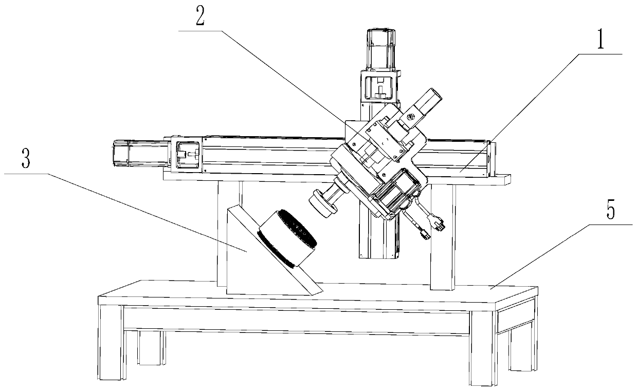
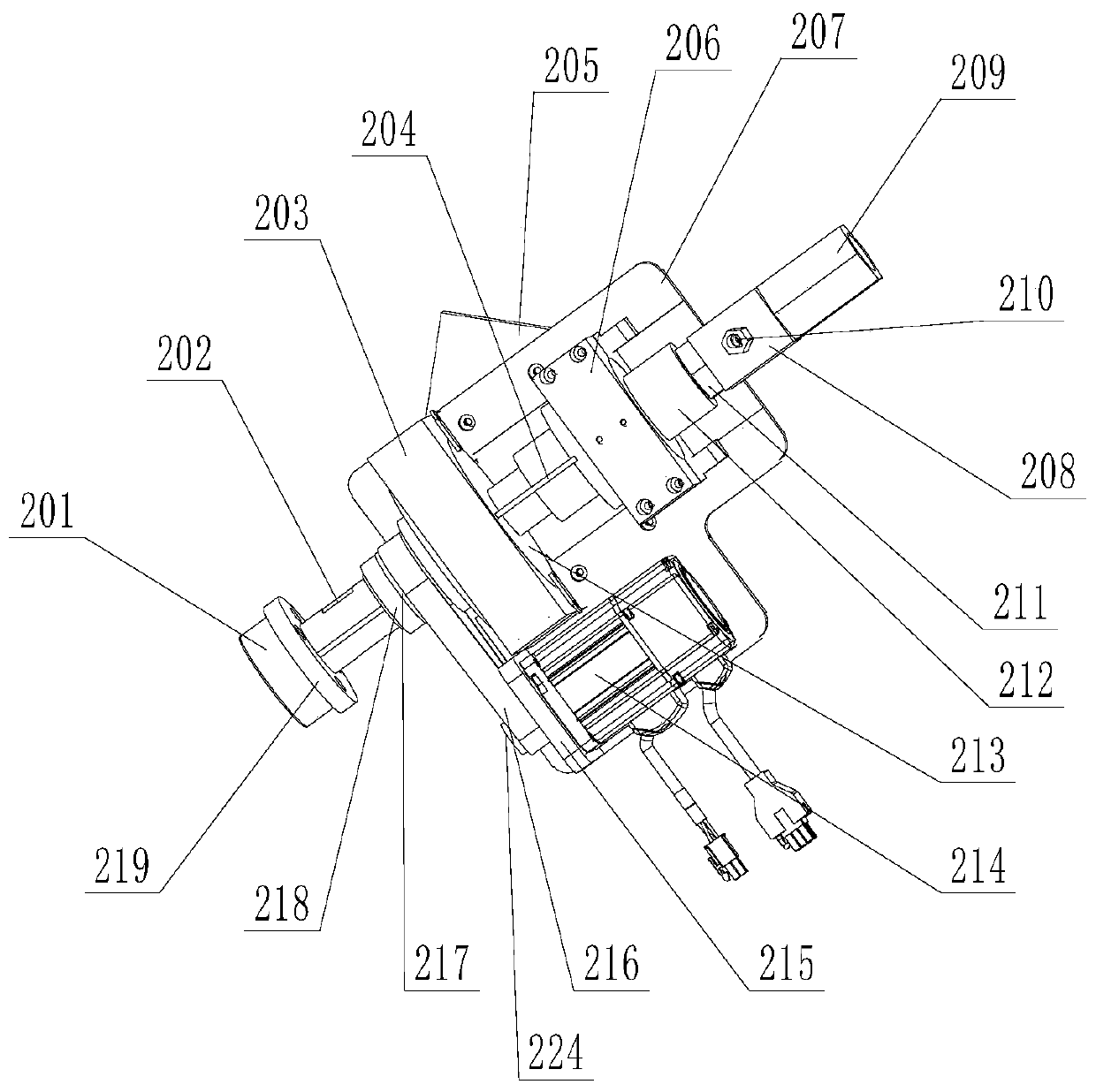
[0052] Such as Figure 1-9 As shown, a negative pressure polishing device for polishing blind holes of conductive workpieces includes a worktable 5, a mobile positioning device 1, a rotating flow channel device 2 and a rotating magnetic field device 3, and the mobile positioning device 1 is installed on the workbench 5. The rotating flow channel device 2 is installed on the mobile positioning device 1 , and the rotating magnetic field device 3 is fixed on the workbench 5 obliquely below the rotating flow channel device 2 .

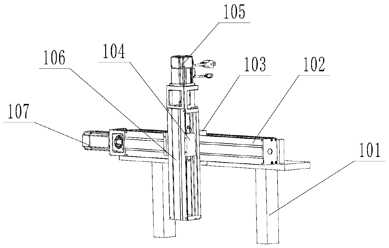
[0053] The mobile positioning device 1 includes a horizontal module mounting frame 101, a horizontal linear module 102, a horizontal module driving motor 107, a vertical linear module 106 and a vertical module driving motor 105, and the horizontal module mounting frame 101 Fixed on the workbench 5; the horizontal linear module 102 is horizontally fixed...


PUM


Abstract

The invention discloses a negative-pressure polishing device and method for blind hole polishing for conductive workpieces. The negative-pressure polishing device for blind hole polishing for the conductive workpieces comprises a workbench, a movable location device, a rotary flow channel device and a rotary magnetic field device, wherein the movable location device is installed on the workbench;the rotary flow channel device is installed on the movable location device; and the rotary magnetic field device is fixed to a part at the inclined lower part of the rotary flow channel device, of theworkbench. According to the negative-pressure polishing device and method for blind hole polishing for the conductive workpieces, blind hole of blind hole workpieces can be polished, and the blind holes of the workpieces to be polished are enabled to be in a negative-pressure state through air extraction, so that abrasive particle flow can much smoothly enters into the blind holes; the abrasive particle flow used in the negative-pressure polishing device and method is liquid metal abrasive particle flow, and metal particles in the liquid metal abrasive particle flow form good contact with thesurfaces of the workpieces to be machined under the action of a rotary magnetic field generated by a three-phase stator coil, micro-cutting is carried out, and mechanical deformation on the surfacesof the blind holes of the workpieces to be machined is avoided; and higher polishing efficiency and better effect are achieved, and the micro-cutting is carried out.

Description

technical field [0001] The invention relates to the field of liquid metal, more specifically, to a negative pressure polishing device and method for polishing blind holes of conductive workpieces. Background technique [0002] 3D printing technology is also called additive manufacturing technology, which is an advanced manufacturing technology called rapid prototyping in China. Its essential principle is discrete and accumulation. The manufacture of three-dimensional solids is transformed into the accumulation of two-dimensional layers and continuous superposition along the forming direction, and finally realizes the manufacture of three-dimensional solids. As the use of 3D printing technology becomes more and more widespread, more and more blind hole products are produced by 3D printing technology. Compared with the through hole, the blind hole refers to the hole that does not pass through. It is widely used in life and industrial production. At the same time, the use of h...

Claims


Application Information

Patent Timeline
Patent Type & Authority Applications(China)
IPC IPC(8): B24B31/10B24B31/12B24B47/12B24B41/02B24B41/06B24B1/00
CPCB24B31/102B24B31/12B24B47/12B24B41/02B24B41/06B24B1/005
Inventor 单晓杭汪佳成张利李研彪叶必卿
Owner ZHEJIANG UNIV OF TECH
Learn More