Driving force receiving assembly of photosensitive drum
A technology of photosensitive drum and driving force, which is applied in the field of processing boxes, can solve problems such as not being in place, difficulty in taking out, poor compatibility, etc., and achieve the effect of stable driving force transmission
- Summary
- Abstract
- Description
- Claims
- Application Information
AI Technical Summary
Problems solved by technology
Method used
Image
Examples
Embodiment 1
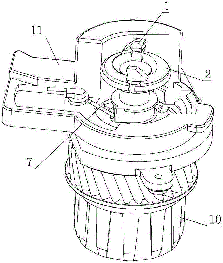
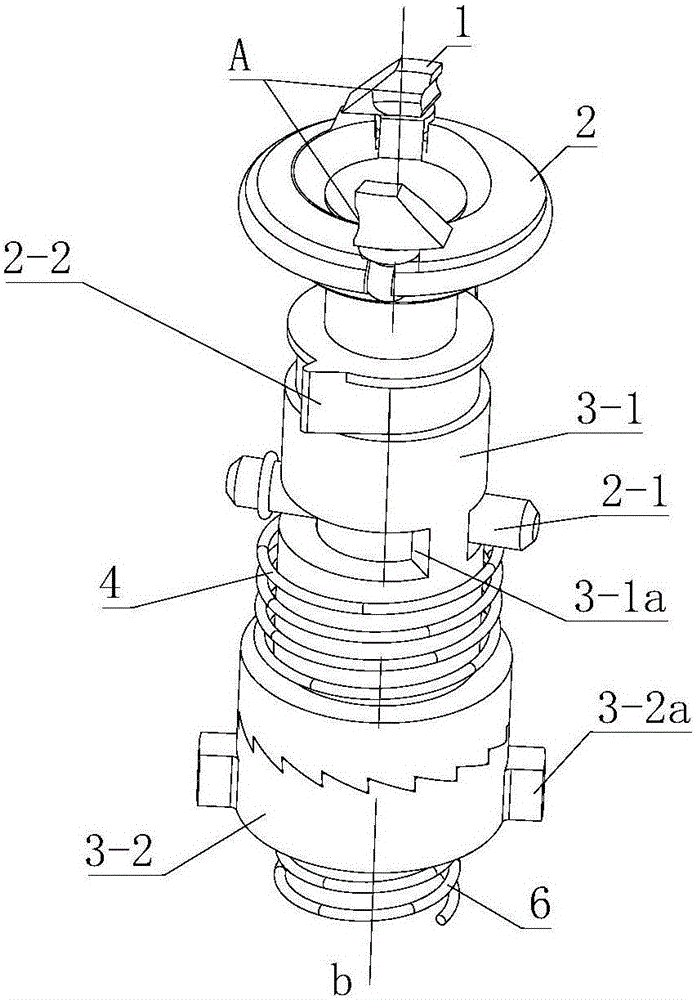
[0057] Such as figure 1 , figure 2 and image 3 As shown, the driving force receiving assembly of the present invention includes a power receiving part 1, a power transmitting part 2, a gear matching part 3 and a position adjusting device. The driving force receiving assembly is used to receive the rotational force of the driving head in the image forming device, and transmit the rotational force to the photosensitive drum through the photosensitive drum gear arranged at the end of the photosensitive drum, so as to drive the photosensitive drum to rotate. The gear fitting part 3 in this embodiment is a split structure, which includes a first fitting part 3 - 1 fitting with the power transmission part 2 and a second fitting part 3 - 2 fitting with the photosensitive drum gear 10 .
[0058] A pair of power receiving parts 1 are symmetrically arranged on the power transmission part 2, and the power receiving part 1 protrudes upward from the power transmission part 2. The side...
Embodiment 2
[0069] Such as Figure 10 as shown, Figure 10The direction indicated by the middle arrow is the predetermined rotational driving direction. The difference between this embodiment and Embodiment 1 is that the limit adjustment device 7 of this embodiment is an elastic swing arm with one end fixed on the gear end cover 11, and the elastic swing arm is made of elastic materials, such as metal shrapnel or Rubber body etc. The power transmission part 2 is provided with a stop protrusion 2-2 protruding from its outer wall. The cross-sectional shape of the stop protrusion 2-2 in this embodiment along the direction perpendicular to the axis of the power transmission part is trapezoidal, but it can also be rectangular . The included angle between the axis a2 of the elastic swing arm and the line a3 between the center point of the limiting protrusion and the rotation centerline of the power transmission part along the rotation direction of the power transmission part is greater than ...
Embodiment 3
[0071] Such as Figure 11 as shown, Figure 11 The direction indicated by the middle arrow is the predetermined rotational driving direction. The difference between this embodiment and the second embodiment is that the limit adjustment device includes a rotating swing arm 7 and an elastic member 7a. The rotating swing arm is hinged on the gear end cover 11 and can rotate around the hinge point. The elastic member 7a is arranged on Between the rotating swing arm and the side wall of the gear end cover, they are respectively connected with the rotating swing arm and the side wall of the gear end cover. The included angle between the axis of the rotating swing arm, the center point of the limit protrusion and the rotation centerline of the power transmission part along the rotation direction of the power transmission part is greater than 0 degrees and less than 90 degrees. During the rotation of the power transmission part 2, when the limit protrusion 2-2 passes the rotating sw...
PUM
 Abstract
Description
Claims
Application Information
 - R&D
- Intellectual Property
- Life Sciences
- Materials
- Tech Scout
- Unparalleled Data Quality
- Higher Quality Content
- 60% Fewer Hallucinations
Browse by: Latest US Patents, China's latest patents, Technical Efficacy Thesaurus, Application Domain, Technology Topic, Popular Technical Reports.
© 2025 PatSnap. All rights reserved.Legal|Privacy policy|Modern Slavery Act Transparency Statement|Sitemap|About US| Contact US: help@patsnap.com


