
Carbon dioxide laser amplification device with controllable pass number

A carbon dioxide, laser amplification technology, applied in laser cooling device, photoplate process exposure device, laser and other directions, can solve problems such as unfavorable laser system operation, affecting laser amplification efficiency, self-excited oscillation, etc., to improve laser amplification efficiency, solve the The effect of low amplification gain and high gain laser amplification

Inactive Publication Date: 2019-12-24
CHANGCHUN INST OF OPTICS FINE MECHANICS & PHYSICS CHINESE ACAD OF SCI
View PDF6 Cites 0 Cited by
  • Summary
  • Abstract
  • Description
  • Claims
  • Application Information

AI Technical Summary

Problems solved by technology

In addition, the above-mentioned amplification technologies all use a linear cavity structure, especially the latter two technologies have a high reflectivity of the cavity mirror, which is very easy to cause self-excited oscillation, which seriously affects the laser amplification efficiency and is not conducive to the operation of the laser system.

Method used


Image

  • Carbon dioxide laser amplification device with controllable pass number

Examples


Embodiment Construction

[0037] The following will clearly and completely describe the technical solutions in the embodiments of the present invention with reference to the accompanying drawings in the embodiments of the present invention. Obviously, the described embodiments are only some, not all, embodiments of the present invention. Based on the embodiments of the present invention, all other embodiments obtained by persons of ordinary skill in the art without making creative efforts belong to the protection scope of the present invention.

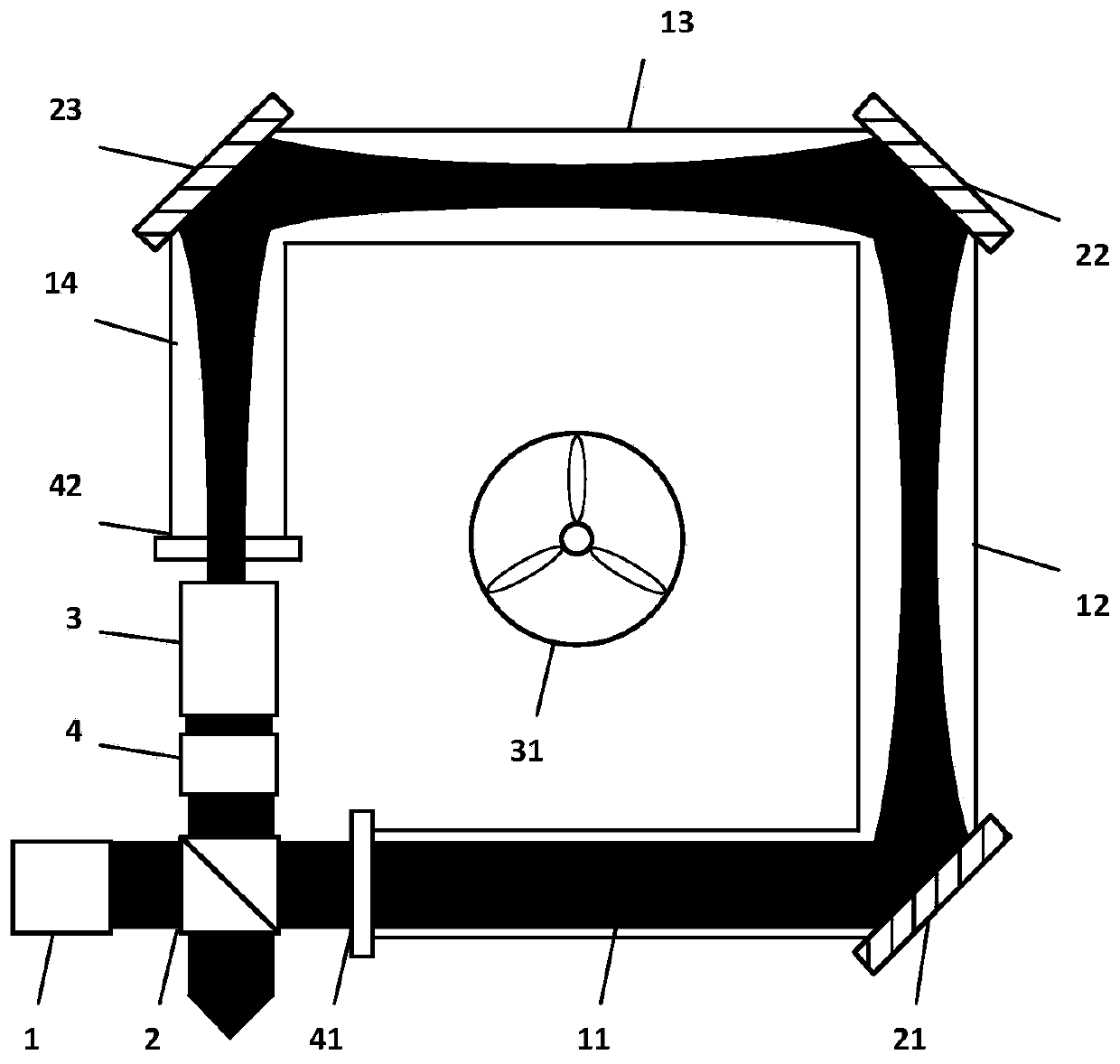
[0038] The invention provides a carbon dioxide laser amplification device with controllable range, such as figure 1shown, including:

[0039] The seed laser 1 is used to output or output a linearly polarized laser beam in combination with a polarizing element;

[0040] Thin film polarizer 2, used for injecting the laser beam output by the seed laser 1 into the ring amplifier after transmission;

[0041] The ring amplifier is used to amplify the laser energy ...


PUM


Abstract

The invention discloses a carbon dioxide laser amplification device with a controllable pass number. The device comprises a seed laser which is used for outputting or combining a polarization elementto output a linear polarization laser beam, a film polaroid used for transmitting or reflecting the laser beam, an annular amplifier used for amplifying laser energy through an annular cavity axial flow laser amplification structure and injecting the laser energy into a light beam conversion system, the light beam conversion system used for performing collimation and size conversion on the laser beam and then injecting the laser beam into an electro-optical switch, and the electro-optical switch used for dynamically adjusting the amplification pass number of the laser beam by regulating and controlling the driving voltage. According to the carbon dioxide laser amplification device, the annular cavity axial flow laser amplification structure is utilized, the self-excited oscillation is effectively restrained, the laser amplification efficiency is improved, meanwhile, the annular amplifier has a compact structure, the size is effectively reduced, by combining a polarization control element, the light beam conversion system and the electro-optical switch, the amplification of any pass number can be realized, the amplification pass number is flexibly controlled, the high-gain laser amplification is realized in a single laser amplifier, and the requirement on the power of injected seed light is relatively low.

Description

technical field [0001] The invention relates to the technical field of extreme ultraviolet lithography light sources, in particular to a carbon dioxide laser amplification device with controllable range. Background technique [0002] The projection lithography technology using extreme ultraviolet light with a wavelength of 13.5nm is considered to be the mainstream technical approach to realize the short-wavelength lithography process. The realization method includes but is not limited to carbon dioxide laser irradiation droplet tin target to generate plasma and then radiate 13.5nm extreme ultraviolet light. This method has the advantages of high conversion efficiency and less debris generation, and is currently a relatively mature 13.5nm extreme ultraviolet light generation technology. Program. [0003] The extreme ultraviolet light generated by laser plasma requires driving carbon dioxide laser to output high power, high repetition rate and short pulse carbon dioxide laser...

Claims


Application Information

Patent Timeline
Patent Type & Authority Applications(China)
IPC IPC(8): H01S3/034H01S3/04H01S3/041H01S3/08H01S3/083H01S3/097H01S3/107G03F7/20
CPCG03F7/70025H01S3/034H01S3/0404H01S3/041H01S3/08059H01S3/0835H01S3/097H01S3/107
Inventor 孙俊杰潘其坤郭劲陈飞张阔于德洋张鲁薇何洋
Owner CHANGCHUN INST OF OPTICS FINE MECHANICS & PHYSICS CHINESE ACAD OF SCI
Learn More