
Oxygen separation device and process

A separation device and process technology, applied in the application field of mixed conductor oxygen-permeable membrane, can solve the problems of large power plant energy consumption, energy consumption reduction, low purity, etc., achieve good economic and social effects, compact and reasonable structure, and widely used Effect

Pending Publication Date: 2019-12-20
NANJING UNIV OF TECH
View PDF6 Cites 1 Cited by
  • Summary
  • Abstract
  • Description
  • Claims
  • Application Information

AI Technical Summary

Problems solved by technology

[0002] At present, there are two methods of oxygen production that are widely used in industry. One is low-temperature air separation oxygen production: it is characterized by large output and high oxygen purity, and can produce other gases and liquids such as nitrogen and argon at the same time, but it consumes a lot of energy and costs High; the second is pressure swing adsorption oxygen production: it is characterized by low purity (purity greater than 92%), small output, but low cost
For large-scale oxygen production, although cryogenic oxygen production technology is relatively mature, it consumes a large amount of power plant energy in the process, accounting for 15% of the investment cost of coal-fired power plants, and there is no possibility of a stepwise decline in energy consumption
However, the pressure swing adsorption oxygen production equipment has the disadvantage of low production capacity, the oxygen production scale is relatively small, up to 150 tons / day, and the oxygen purity is low, only 90-95%.

Method used


Image

  • Oxygen separation device and process

Examples


Embodiment 1

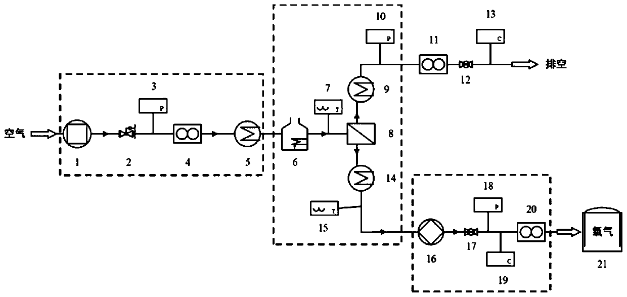
[0018] Such as figure 1 As shown, an oxygen separation device is characterized in that the device includes an air pressurization system, an oxygen separation system, a vacuum system and an air storage tank, wherein the air pressurization system is successively composed of an air compressor 1 through a pressure reducing valve 2, the first A pressure detector 3, the first flow detector 4 are connected with the first heat exchanger 5, and the feed side of the air compressor 1 is communicated with the atmosphere; the oxygen separation system consists of a heater 6, a membrane module 8, and a second heat exchanger 9. The third heat exchanger 14 is composed of one side of the heater 6 connected with the first heat exchanger 5, and the other side is connected with the membrane module 8 through the first temperature detector 7, and one side of the membrane module 8 is connected with the second heat exchanger 9, connected to the exhaust pipe through the second pressure detector 10, the...

Embodiment 2

[0021] The oxygen separation device and separation process are the same as in Example 1. After the air in the atmosphere is compressed by the air compressor 1 in the air pressurization system, it enters the membrane module 8 and the heater 6 of the oxygen separation system to be heated, and the air compressor The outlet pressure is 5atm, and the feed air is heated by the thermal energy of evacuating oxygen-depleted air and product oxygen. The first heat exchanger 5, the second heat exchanger 9, and the third heat exchanger 14 adopt partition wall heat exchangers, and exchange heat through a mixture of heat transfer medium water and ethanol. The energy required by the heater 6 and the first heat exchanger 5, the second heat exchanger 9, and the third heat exchanger 14 is supplemented by electricity, and the oxygen that is separated by the multi-channel mixed conductor oxygen-permeable membrane in the membrane module 8 is The temperature is controlled at 600°C. Among them, the ...

Embodiment 3

[0023] The oxygen separation device and separation process are the same as in Example 1. After the air in the atmosphere is compressed by the air compressor 1 in the air pressurization system, it enters the membrane module 8 and the heater 6 of the oxygen separation system to be heated, and the air compressor The outlet pressure is 30atm, and the heat energy of boiler exhaust gas and steam is used to heat the feed air. The first heat exchanger 5, the second heat exchanger 9, and the third heat exchanger 14 adopt hybrid heat exchangers, and exchange heat through a mixture of heat transfer medium ethylene glycol and oil. The energy required by the heater 6 and the first heat exchanger 5, the second heat exchanger 9, and the third heat exchanger 14 is supplemented by steam, and the temperature of the oxygen separated by the multi-channel mixed conductor oxygen-permeable membrane in the membrane assembly 8 Controlled at 1050°C. Among them, the multi-channel mixed conductor oxygen...


PUM


Abstract

The invention relates to an oxygen separation device and process. The oxygen separation device provided by the invention is established by using a mixed conductor oxygen permeable membrane as a base and comprises an air pressurizing system, an oxygen separation system, a vacuuming system and necessary pipelines, valves and gas storage tanks. By adopting the oxygen separation device, air in the atmosphere can be directly separated to obtain oxygen of which the purity is as high as 99.99%, continuous production of high-purity oxygen can be achieved, large-scale oxygen supply demands can be met,in addition, a medium / small-size direct oxygen supply device which is easy to move and is convenient and flexible can be manufactured, the device is small in floor space, simple and convenient in operation process and reliable in operation, and the service life of an oxygen permeable material is long. Compared with the prior art, the device adopts the cheap air as a raw material, is capable of continuously making high-purity oxygen of which the purity is 99.99%, uninterruptedly providing oxygen supply for 24 hours and meeting industrial and laboratory requirements, and has very good application prospects.

Description

technical field [0001] The invention relates to an oxygen separation device and a process, in particular to an oxygen separation device and a process for a multi-channel mixed conductor oxygen permeable membrane, belonging to the technical field of mixed conductor oxygen permeable membrane applications. Background technique [0002] At present, there are two methods of oxygen production that are widely used in industry. One is low-temperature air separation oxygen production: it is characterized by large output and high oxygen purity, and can produce other gases and liquids such as nitrogen and argon at the same time, but it consumes a lot of energy and costs Second, pressure swing adsorption oxygen production: characterized by low purity (purity greater than 92%), small output, but low cost. For large-scale oxygen production, although cryogenic oxygen production technology is relatively mature, it consumes a large amount of power plant energy in the process, accounting for ...

Claims


Application Information

Patent Timeline
Patent Type & Authority Applications(China)
IPC IPC(8): C01B13/02
CPCC01B13/0255C01B2210/0042
Inventor 刘郑堃金万勤倪书阳张广儒
Owner NANJING UNIV OF TECH
Learn More