Fuel cell device for photocatalytic degradation of oil smoke and working method of fuel cell device

A fuel cell and photocatalytic technology, which is applied in the field of oil fume purification, can solve problems such as the inability to apply roof oil fume emission treatment, large consumption of auxiliary substances, and air pollution, and achieve the effects of simple structure, reduced power consumption, and reduced pollution

Active Publication Date: 2019-12-20
LIAONING JIANZHU VOCATIONAL UNIV
View PDF4 Cites 0 Cited by
  • Summary
  • Abstract
  • Description
  • Claims
  • Application Information

AI Technical Summary

Problems solved by technology

[0003] In the emission sources of residential buildings and commercial buildings with catering functions, the oily fume is directly discharged through the range hood without treatment, or concentratedly discharged to the outdoor environment through the roof flue. Any treatment will cause serious pollution to the atmosphere. Studies have shown that the instantaneous PM2.5 emission concentration during the three meals of family meals is as high as 200ug / m 3
[0004] Based on this, it is urgent to develop a high-efficiency treatment method for cooking fume from the roof of the building. The existing methods for the treatment of soot particles mainly include: mechanical removal method, electrostatic method, washing method, adsorption method, catalytic combustion method And the combination of these methods, but these methods have certain defects, such as high energy consumption, large consumption of auxiliary substances, etc., and cannot be applied to the treatment of oil fume emission on the roof

Method used


Image

  • Fuel cell device for photocatalytic degradation of oil smoke and working method of fuel cell device
  • Fuel cell device for photocatalytic degradation of oil smoke and working method of fuel cell device

Examples


Embodiment 1

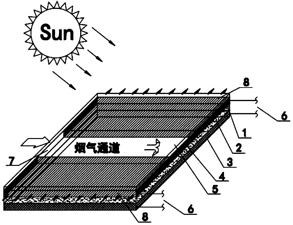
[0031] See attached figure 1 , a fuel cell device for photocatalytic degradation of soot, comprising: an anode 1, a proton exchange membrane 2, an air cathode 3, a sealing plate 4, quartz glass 5, an external circuit 6, a flue gas inlet 7 and a flue gas outlet 8.

[0032] The anode 1, the proton exchange membrane 2 and the air cathode 3 are tightly combined by conductive tape to form a composite electrode of a sandwich structure; and the sequence of tight combination is that the proton exchange membrane 2 is sandwiched between the anode 1 and the air cathode 3 middle;

[0033] The quartz glass 5 and the sealing plate 4 are closely combined with the anode 1 to form a flue gas flow channel; and the sealing plate 4 is fixed on the side of the anode 1;

[0034] One end of the external circuit 6 is respectively connected to the anode 1 and the air cathode 3, and the other end is connected to the power storage device; the unpurified flue gas enters the device through the flue gas i...

Embodiment 2

[0038] See attached figure 2 , a method for using a photocatalytic degradation oil fume fuel cell device, comprising the following steps:

[0039] ①During the meal time period, the flue gas discharged from the flue on the roof enters a device for photocatalytic degradation of oil fume fuel cells through the flue gas inlet 7, and the anode 1 and air cathode 3 in the device undergo the following reactions:

[0040] a Anode reaction: when the flue gas enters the device through the flue gas inlet 7 and flows through the anode 1, the foamed nickel-CNTs composite material of the anode 1 traps the particles in the flue gas in the inside of the anode 1 through filtration, and the flue gas Under the action of light, the gaseous pollutants in the gaseous pollutants are decomposed into carbon dioxide and water through the photocatalyst loaded on the composite material of the anode 1 by photocatalysis, and the gaseous pollutants are discharged from the flue gas outlet 8 to achieve the pu...


PUM


Abstract

The invention provides a fuel cell device for photocatalytic degradation of oil smoke and a working method of the fuel cell device. The fuel cell device is characterized by comprising an anode, a proton exchange membrane, an air cathode, a sealing plate, quartz glass, external circuits, a flue gas inlet and flue gas outlets. The fuel cell device and the working method of the fuel cell device havethe beneficial effects that characteristics of low energy consumption of a photocatalysis technology and a good deep oxidation effect on organic pollutants are utilized to realize effective treatmentand degradation of particles and gaseous pollutants in oil smoke, and electric energy generated by degradation is used for power supply of building public equipment, so that secondary utilization of waste pollutants is realized.

Description

technical field [0001] The invention belongs to the technical field of oil fume purification, and relates to a technical method for removing fine particles in unorganized oil fume and purifying harmful gases, in particular to a photocatalytic degradation oil fume fuel cell device and a working method thereof. Background technique [0002] The main cooking methods in my country are frying, frying, frying, roasting, etc., which are prone to produce a large amount of soot aerosol, which contains fatty acids, alkanes, alkenes, aldehydes, ketones, alcohols, aromatic compounds and heterocyclic compounds, etc. These substances It exists in oil fume in the form of particle phase and gas phase. [0003] In the emission sources of residential buildings and commercial buildings with catering functions, the oil fume is directly discharged through the range hood without treatment, or concentratedly discharged to the outdoor environment through the roof flue. Any treatment will cause rela...

Claims


Application Information

Patent Timeline
IPC IPC(8): B01D53/86B01D49/00B01D53/38B01D53/44H01M8/1007
CPCB01D53/8678B01D53/8687B01D49/00H01M8/1007B01D2259/80B01D2258/0283B01D2255/802B01D2255/20707B01D2255/104B01D2255/1021H01M2008/1095Y02E60/50
Inventor 赵丽丽
Owner LIAONING JIANZHU VOCATIONAL UNIV
Why Eureka
Try Eureka