Two-section downdraught bed ironmaking system and ironmaking process

An entrained-flow, two-stage technology is applied in the field of two-stage descending entrained-flow ironmaking technology, which can solve the problems of low reduction efficiency, low waste heat recovery rate, no simple process, low energy consumption, etc., and achieves improved reduction efficiency, The effect of reduced footprint and reduced complexity

Active Publication Date: 2019-12-17
SHANDONG UNIV
View PDF8 Cites 3 Cited by
  • Summary
  • Abstract
  • Description
  • Claims
  • Application Information

AI Technical Summary

Problems solved by technology

Existing non-blast furnace ironmaking technologies include direct reduction methods of gas reduction, direct reduction methods using solid reducing agents, and typical smelting reduction processes such as Corex process, Finex process, and HIsmelt process, but each of the above processes has different problems, such as reduction Low efficiency, low recovery rate of waste heat, still need some metallurgical coke, etc., no ironmaking process with simple process and low energy consumption

Method used


Image

  • Two-section downdraught bed ironmaking system and ironmaking process
  • Two-section downdraught bed ironmaking system and ironmaking process

Examples


Embodiment 1

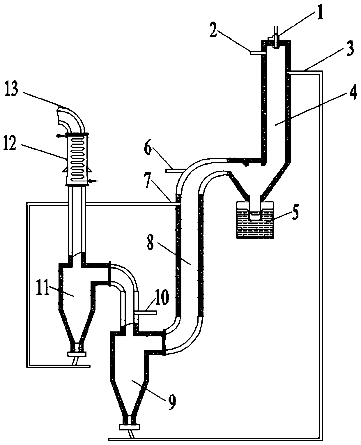
[0052] Such as figure 1 As shown, a two-stage downflow bed ironmaking process device (arrangement 1) structure includes a melting furnace section 4, which is an airflow down bed, a basic combustion / gasifier 1 is set on the top, and the upper side is The first inlet 2 of coke (coal) powder (air, water vapor), a pre-reduction ore inlet-second inlet 3 is set at a distance below it; the ore pre-reduction furnace section 8 is an airflow down bed, and the upper side is a pre-reduction Hot ore powder inlet-fourth inlet 7, the lower part is connected to the inlet of the pre-reduced ore powder separator-the first separator 9; the melting furnace section 4 and the ore powder pre-reduction furnace section 8 are connected through the slag pool 5; cooling and tempering and tempering The medium inlet-the third inlet 6 is set at the connecting pipe between the slag pool 5 and the slag pre-reduction furnace section 8; the upper outlet of the first separator 9 is connected to the preheating cycl...

Embodiment 2

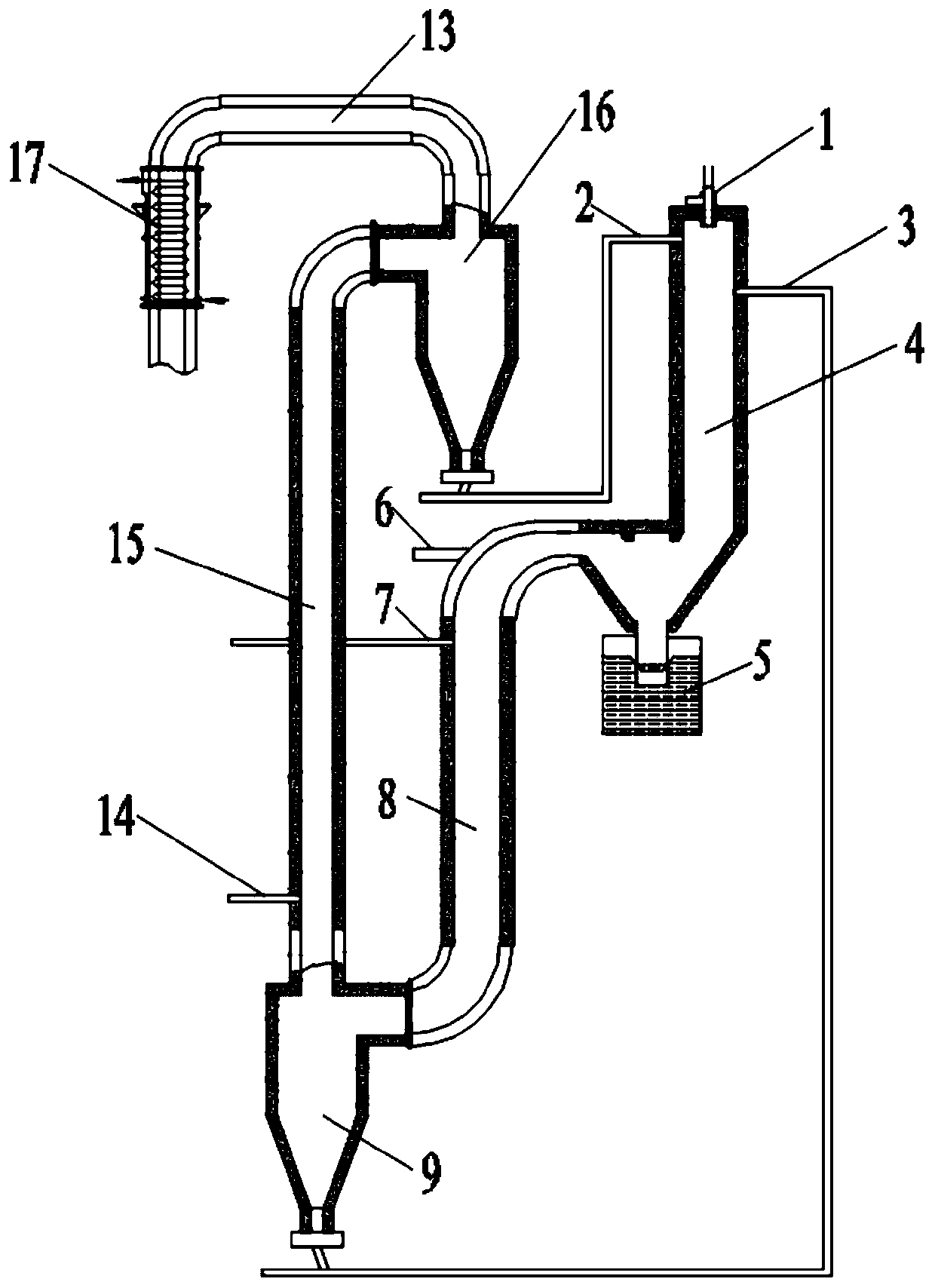
[0063] Such as figure 2 Shown is another implementation of this application. A two-stage downflow bed ironmaking process (arrangement 2) structure includes a melting furnace section 4, the melting furnace section 4 is an airflow down bed, the top is set up with a basic combustion / gasifier 1, and the upper side is coke powder ( (Air, water vapor) inlet-first inlet 2, a pre-reduced mineral powder inlet-second inlet 3 is set at a distance below it; mineral powder pre-reduction furnace section 8 is a flow down bed, and the upper side is a mineral powder inlet-fourth Inlet 7, the lower part is connected to the inlet of the pre-reduced mineral powder separator-the first separator 9; the melting furnace section 4 and the mineral powder pre-reduction furnace section 8 are connected through the slag pool 5; the cooling and tempering medium inlet-the third inlet 6 is set At the connection pipeline between the slag pool 5 and the slag pre-reduction furnace section 8; the upper outlet of...


PUM


Abstract

The invention discloses a two-section downdraught bed ironmaking system and ironmaking process. The system comprises a melting furnace section, a pre-reduction furnace section and a first separator. The melting furnace section is arranged vertically and downwards, a basic combustion / gasification device is arranged at the top of the melting furnace section, a first inlet and a second inlet are arranged on the lower portion of the basic combustion / gasification device, and the first inlet and the second inlet are evenly arranged along the side wall of the basic combustion / gasification device. A contact circle is formed in the basic combustion / gasification device, and the second inlet is located below the first inlet. The first inlet is connected with a coke powder / pulverized coal source, an air source and a steam source. A slag pool is arranged at the bottom of the melting furnace section and is provided with a slag discharging device and a tapping device, and the downstream part of the slag pool serves as the outlet end.The pre-reduction furnace section is arranged vertically and downwards, the top of the pre-reduction furnace section is connected with the outlet end of the melting furnace section, a third inlet and a fourth inlet are arranged on the upper portion of the pre-reduction furnace section, an outlet is arranged at the bottom of the pre-reduction furnace section, the third inlet is connected with a temperature adjusting and tempering medium source, and the fourth inlet is connected with an iron ore powder source. An inlet of the first separator is connected with the outlet of the pre-reduction furnace section, and a bottom outlet of the first separator is connected with the second inlet through a conveying pipeline.

Description

Technical field [0001] The invention belongs to the technical field of metal smelting, and particularly relates to a two-stage downdraft bed ironmaking process. Background technique [0002] Disclosure of the background information is only intended to increase the understanding of the overall background of the present invention, and is not necessarily regarded as an acknowledgement or in any form suggesting that the information constitutes the prior art known to those of ordinary skill in the art. [0003] The blast furnace ironmaking method is currently the main method of producing steel, and its dominant position is not expected to change in the short term. This method is a continuous metallurgical method for reducing iron ore to iron in a blast furnace. The smelting process is as follows: load iron ore, coke, and flux for slagging from the top of the furnace according to the specified ratio, and make the furnace The throat material surface maintains a certain height, coke and o...

Claims


Application Information

Patent Timeline
Patent Type & Authority Applications(China)
IPC IPC(8): C21B13/10C21B13/14
CPCC21B13/10C21B13/14C21B13/0006
Inventor 马春元赵媛王涛周滨选周振峰陈娟
Owner SHANDONG UNIV
Why Eureka
Try Eureka