Household natural gas heat supply system

A heating system and natural gas technology, applied in the field of heating systems and domestic natural gas heating systems, can solve the problems of insufficient utilization of waste heat from flue gas, poor heat exchange performance of heat exchange devices, and heavy maintenance and management workload, etc., to achieve structural Simple, sufficient heat exchange, and the effect of improving air quality

Pending Publication Date: 2019-12-06
HEBEI UNIV OF TECH
View PDF6 Cites 2 Cited by
  • Summary
  • Abstract
  • Description
  • Claims
  • Application Information

AI Technical Summary

Problems solved by technology

The collective heating system is mainly composed of boiler rooms, water supply pipes and user heating equipment. Its engineering volume is huge, the system is complicated, the energy consumption is large, the thermal efficiency is low, and it requires a lot of manpower and material resources. It is not suitable for winter heating in southern my country.
Heating in winter, the room is closed for a long time, the oxygen content of the air decreases, and the water content in the air decreases, which leads to indoor stuffiness and dry air, which makes people feel uncomfortable
[0003] In addition, the heat exchange performance of the heat exchange device is poor, and the waste heat of the flue gas is not fully utilized, which are the main problems existing in the prior art
In the existing patented technology (such as high-efficiency coil boiler CN201917072U), the furnace body is divided into a heating furnace and a preheating furnace to preheat the water, which improves the reuse of waste heat in the flue and improves the thermal efficiency of the boiler; but This technology needs to install fan coil units at the end of each room for the user’s heating equipment, as well as perform daily maintenance and maintenance, and the maintenance and management workload is heavy; and the fan coil units perform heat conversion again, reducing the heating efficiency

Method used


Image

  • Household natural gas heat supply system
  • Household natural gas heat supply system
  • Household natural gas heat supply system

Examples


Embodiment Construction

[0022] In order to illustrate the technical solution of the present invention more clearly, the present invention will be further introduced and described below in conjunction with the embodiments and accompanying drawings.

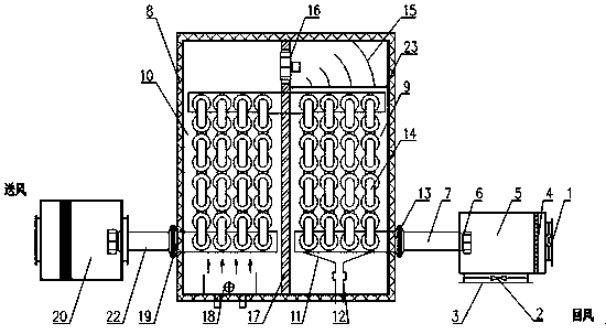
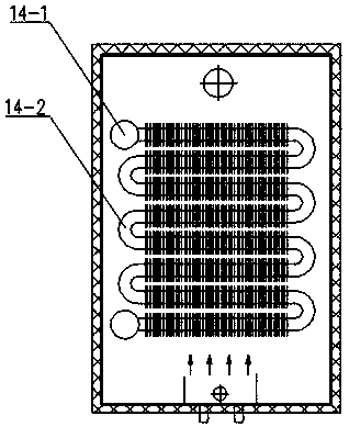
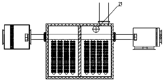
[0023] Domestic natural gas heating system of the present invention (abbreviation heating system, see Figure 1-3 ), characterized in that the heating system includes a fresh air device, a heating device and a humidifier, and the three are connected through an air supply pipeline. The fresh air device includes a new return air outlet, a filter and a fan; the heating device is divided into a preheating chamber (right) and a heating chamber (left); the preheating chamber is placed with a condensation pan and a part of the serpentine tube heat exchanger, and the smoke is exhausted The smoke exhaust pipe is arranged horizontally behind the preheating chamber; the combustion chamber and the other part of the serpentine heat exchanger are placed in the heating ...


PUM


Abstract

The invention relates to a household natural gas heat supply system. The system comprises a casing, a fresh air device, a heating device and a humidifier. The system is characterized in that the freshair device and the humidifier are mounted in a kitchen ceiling of a user and connected with the heating device through an air supply pipeline; the fresh air device comprises a fresh air return port,a filter net and a fan; the heating device is divided into a preheating cavity on the right side and a heating cavity on the left side; a condensate water disc and one part of an S-shaped tubular heatexchanger are placed in the preheating cavity, and a smoke exhaust pipe is horizontally arranged behind the preheating cavity; and a combustion chamber and the other part of the S-shaped tubular heatexchanger are placed in the heating cavity, and air in the S-shaped heat exchanger in the heating cavity communicates with the preheating cavity through a main pipe. Flue gas produced by combustion of natural gas is used for directly heating the air, low-temperature flue gas preheats cold air, and the temperature of exhausted flue gas is decreased.

Description

technical field [0001] The invention relates to a heating system and belongs to the technical field of heating equipment. Specifically, it is a household natural gas heating system. Background technique [0002] my country has a vast territory with a large span from north to south. Centralized heating is often used in the northern region, while the southern region does not have a heating system due to the short winter cycle and high temperature. The collective heating system is mainly composed of boiler rooms, water supply pipes and user heating equipment. Its engineering volume is huge, the system is complex, the energy consumption is large, the thermal efficiency is low, and it requires a lot of manpower and material resources. It is not suitable for winter heating in southern my country. Heating in winter, the room is closed for a long time, the oxygen content of the air decreases, and the water content in the air decreases, which leads to indoor stuffiness and dry air,...

Claims


Application Information

Patent Timeline
Patent Type & Authority Applications(China)
IPC IPC(8): F24D15/00F24F7/007F24F13/28F24F13/20F24F13/22F24H3/04F24H9/18F23J15/06F24F6/00
CPCF24D15/00F24F7/007F24F13/28F24F13/20F24F13/222F24H3/0488F24H9/1881F23J15/06F24F6/00Y02E20/30
Inventor 闵春华朱仙仙王坤谢立垚杨旭光
Owner HEBEI UNIV OF TECH
Why Eureka
Try Eureka