
Non-dismounting nonmetal bottom plate solid mold composite slab, corresponding floor structure and floor construction method

A laminated board, non-metal technology, applied in the direction of floor slabs, building components, building structures, etc., can solve the problem of low bonding strength between blocking materials and surrounding materials, large workload of metal plate removal, and inability to form protective layer thickness, etc. It can reduce the investment of production equipment and facilities, save the dismantling process, and shorten the production cycle.

Pending Publication Date: 2019-11-26
ZHONGQINGDA TECH HLDG CO LTD +1
View PDF5 Cites 2 Cited by
  • Summary
  • Abstract
  • Description
  • Claims
  • Application Information

AI Technical Summary

Problems solved by technology

[0005] The existing reinforced truss concrete composite slab effectively reduces the complexity of on-site formwork support, and does not need to remove the formwork. There are certain defects: First, the prefabrication of the lower concrete layer in the factory not only greatly prolongs the production cycle, but also requires a series of special equipment and facilities such as concrete mixing, pouring and maintenance in addition to conventional mechanical processing equipment, which greatly increases In addition to occupying a large area, the requirements for the load-bearing capacity of the factory building have been greatly increased, and the working environment has been seriously deteriorated, which in turn makes the cost of this prefabricated concrete much higher than that of poured concrete on site, and significantly increases the cost of transportation and storage. associated costs; and the second is that connecting reinforcement (typically extending longitudinal and / or transverse reinforcement in a precast concrete layer from the ends or sides) is often erected on site by supports (usually reinforced beams or The obstruction of the steel bars on the wall), because the connecting steel bars are consolidated on the prefabricated concrete layer, the exposed part is short and not easy to bend, it is very difficult to bypass the blocking of the supporting steel bars, and the connecting steel bars often have to be cut off in practice. This will seriously affect the connection strength; third, especially for two-way slabs, the cast-in-place slab belt formed by the gap between prefabricated concrete slabs is relatively wide, which will still cause a large amount of formwork removal; The bonding strength between layers of concrete is significantly lower than the concrete strength of one job, which affects the quality of the floor slab and is prone to cracks
In addition, when a metal plate is placed on the bottom of the precast concrete slab, although it is convenient or simplifies the related process, the workload of removing the metal plate is very large, and the removed metal plate usually has a lot of damage, which affects its reuse and causes certain damage. Waste, although the exposed truss reinforcement after removing the metal plate cannot be seen from the outside after sealing, the sealing material cannot form an effective protective layer thickness, and the bonding strength between the sealing material and the surrounding materials is also low, and the surface layer is prone to peeling problems such as steel corrosion and exposure

Method used


Image

  • Non-dismounting nonmetal bottom plate solid mold composite slab, corresponding floor structure and floor construction method
  • Non-dismounting nonmetal bottom plate solid mold composite slab, corresponding floor structure and floor construction method
  • Non-dismounting nonmetal bottom plate solid mold composite slab, corresponding floor structure and floor construction method

Examples


Embodiment Construction

[0032] The present invention will be further described below with reference to the accompanying drawings.

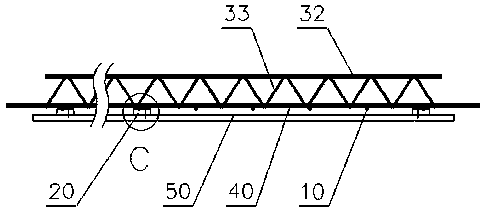
[0033] like Figure 1-18As shown, the non-demolition-free non-metal base plate solid-form laminated board (referred to as the fixed-form laminated board) provided by the present invention includes a base plate 50, a steel truss 30 and a steel mesh located above the base plate, and the steel mesh can be arranged on the steel truss and the steel mesh. Between the cushion blocks, in order to facilitate processing, the bottom plate is made of a non-metallic plate, and there is a gap between the bottom plate of the steel bar truss and the upper surface of the bottom plate.

[0034] There is no precast concrete layer for this kind of solid-form laminated board, especially for the strength of the bottom plate, but it can be sprayed with an interface layer, an oxygen-insulating fire-proof layer or an anti-corrosion layer according to actual needs.

[0035] The steel bar truss c...


PUM


Abstract

The invention discloses a non-dismounting nonmetal bottom plate solid mold composite slab, a corresponding floor structure and a floor construction method. The solid mold composite slab comprises a bottom plate, one reinforcing mesh and multiple steel bar trusses, wherein the reinforcing mesh and the multiple steel bar trusses are located above the bottom plate; the bottom plate is made of nonmetal materials, gaps are reserved between bottom plates of the steel bar trusses and the upper surface of the bottom plate, the floor takes the non-dismounting nonmetal bottom plate solid mold compositeslab as a permanent mold plate of a bottom mold, and a cast-in-place concrete layer is arranged on the permanent mold plate. According to the construction method, the non-dismounting nonmetal bottom plate solid mold composite slab serves as the permanent mold plate, a supporting system is arranged, the non-dismounting nonmetal bottom plate solid mold composite slab is mounted in place to form thefloor bottom mold, the cast-in-place concrete layer is poured on the bottom mold, and after solidification, the non-dismounting nonmetal bottom plate solid mold composite slab is not dismounted. The non-dismounting nonmetal bottom plate solid mold composite slab is simple in preparing process, short in production period, low in cost, and convenient to operate on the site construction, the formed floor meets the habitual texture of the person, and decoration is convenient.

Description

technical field [0001] The invention relates to a non-demolition-free non-metal base plate solid-form laminated board, a floor using the solid-form laminated board and a construction method for the floor, and belongs to the field of construction. Background technique [0002] Formwork support and dismantling of cast-in-place floor slabs is very complicated, time-consuming and labor-intensive, which not only seriously restricts the production efficiency, but also increases the construction cost, and increases the labor intensity and deteriorates the labor environment. [0003] To simplify the process, attempts have been made to use permanent formwork (or fixed formwork), which is cemented with the poured-in-place concrete (cast-in-place concrete layer) to form part of the floor structure, thus at least eliminating the need for formwork removal Among them, the more successful technologies include profiled steel plates and reinforced truss concrete laminates. Because the mater...

Claims


Application Information

Patent Timeline
IPC IPC(8): E04B5/36E04G21/00
CPCE04B5/36E04G21/00
Inventor 侯建群
Owner ZHONGQINGDA TECH HLDG CO LTD
Learn More