Interference distributed optical fiber acoustic sensing device and sensing method

A technology of sensing device and sensing method, which is applied in the direction of measuring device, ultrasonic wave/sonic wave/infrasonic wave, instrument, etc., can solve the problems of limiting the application range of phase-sensitive optical time domain reflection technology and low scattering coefficient, and meet the requirements of different The effect of sensing spatial resolution requirements, improving signal-to-noise ratio, and increasing speed and simplicity

Active Publication Date: 2019-11-19
TIANJIN UNIV
View PDF6 Cites 11 Cited by
  • Summary
  • Abstract
  • Description
  • Claims
  • Application Information

AI Technical Summary

Problems solved by technology

Due to the random distribution of scattering points in the fiber, the low Rayleigh scattering coefficient, and the use of simple single-frequency pulses, it is difficult for the traditional phase-sensitive optical time-domain reflection sensing technology to achieve high-precision detection of external acoustic vibrations. Full-information waveform measurement including amplitude, frequency and phase, which limits the scope of application of phase-sensitive optical time-domain reflectometry in practical engineering applications

Method used


Image

  • Interference distributed optical fiber acoustic sensing device and sensing method
  • Interference distributed optical fiber acoustic sensing device and sensing method
  • Interference distributed optical fiber acoustic sensing device and sensing method

Examples


Embodiment Construction

[0032] The technical solution of the present invention will be described in further detail below in conjunction with the accompanying drawings and specific embodiments.

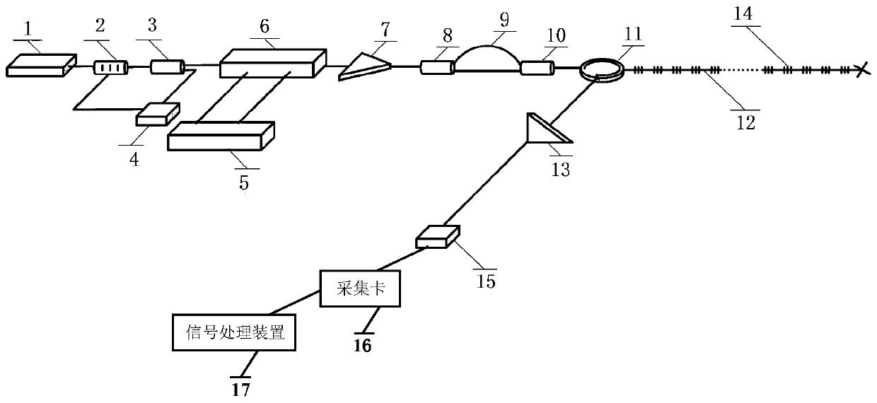
[0033] Such as figure 1 As shown, it is a structural schematic diagram of the interference distributed optical fiber acoustic sensing device of the present invention. The structure of the device includes a light source 1, a polarization controller 2, a polarization beam splitter 3, a first photodetector 4, a modulation signal generating device 5, a dual-parallel Mach-Zehnder electro-optic modulator 6, a first optical amplifier 7, a first 1 ×2 fiber coupler 8, time-delay fiber 9, second 1×2 fiber coupler 10, fiber circulator 11, sensing fiber 12, second optical amplifier 13, microreflection grating array 14, second photodetector 15 , acquisition card 16 and signal processing device 17; Wherein:

[0034] The light source 1 selects a narrow linewidth laser with a wavelength in the C+L band;

[0035] The polar...


PUM


Abstract

The invention discloses an interference distributed optical fiber acoustic sensing device. The device includes a light source (1), a polarization controller (2), a polarization beam splitter (3), a modulation signal generating device (5), a first light amplifier (7), a first 1*2 fiber coupler (8), a time-delay fiber (9), a second 1*2 fiber coupler (10), a fiber circulator (11), a sensing fiber (12), a second light amplifier (13), a micro-reflective grating array (14), a second photodetector (15), an acquisition card (16), and a signal processing device (17) which are connected in sequence. Compared with the prior art, the device and the method can increase rapidity and simplicity of sound sensing demodulation, and different sensing spatial resolution requirements can be satisfied through flexible arrangement of spacing of a micro-reflective grating.

Description

technical field [0001] The present invention relates to the technical field of coherent optical time domain reflection and signal demodulation, in particular to an interference distributed optical fiber acoustic sensing device and sensing method based on micro-reflection gratings and double-sweep frequency modulation pulses. Background technique [0002] Phase-sensitive Optical Time Domain Reflectometer (Phase-sensitive Optical Time Domain Reflectometer, ) sensing technology has a wide range of applications and demands in building structure health monitoring, mineral detection, submarine optical cable monitoring, and underwater monitoring. Phase-sensitive optical time-domain reflection sensing technology injects light pulses, analyzes the back Rayleigh scattered light signals along the optical fiber, and obtains the optical phase information of the sensing optical fiber, so as to detect the optical fiber caused by external vibration and acoustic signals in real time. The p...

Claims


Application Information

Patent Timeline
Patent Type & Authority Applications(China)
IPC IPC(8): G01H9/00
CPCG01H9/004
Inventor 江俊峰刘铁根刘琨梁冠华王双丁振扬张学智马喆陈文杰
Owner TIANJIN UNIV
Why Eureka
Try Eureka