Non-annealing integral forming process of stainless steel water tank

An integral molding, stainless steel technology, applied in the field of kitchen utensils, can solve the problems of negative impact on the appearance of the sink, affect the use of the sink, and easy peeling of the coating, and achieve the effect of improving the surface performance of the sink, improving efficiency, and improving scratch resistance.

Active Publication Date: 2019-11-19
NINGBO OULIN IND CO LTD
View PDF6 Cites 2 Cited by
  • Summary
  • Abstract
  • Description
  • Claims
  • Application Information

AI Technical Summary

Problems solved by technology

Also, accidentally drop a sharp knife into the sink or collide with the upper edge of the sink
Also, when washing cups and saucers in the sink, ceramic coffee mugs and dinner plates are often scratched by accidentally dragging them across the sink surface
In the prior art, attempts have been made to apply a protective surface coating to the surface of the sink. In some cases, this coating can negatively affect the appearance of the sink and the coating is more likely to peel off the surface of the sink base or crack , affecting the use of the sink

Method used


Image

  • Non-annealing integral forming process of stainless steel water tank
  • Non-annealing integral forming process of stainless steel water tank
  • Non-annealing integral forming process of stainless steel water tank

Examples


Embodiment 1

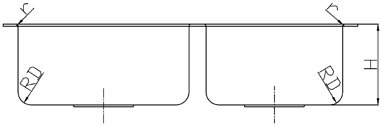
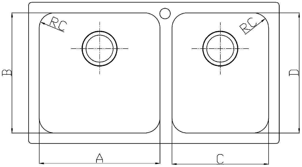
[0043] In this embodiment, the stainless steel water tank has double grooves such as figure 1 with figure 2 As shown, there are two tanks. The length and width of the two tanks are A, B, C, and D respectively. The depth of the two tanks is H. The top of the tank forms a rounded corner RC and the bottom forms a rounded corner. RD, the notch of the sink forms a fillet r with the edge.

[0044] The stainless steel water tank double tank preparation process of the present embodiment is as follows:

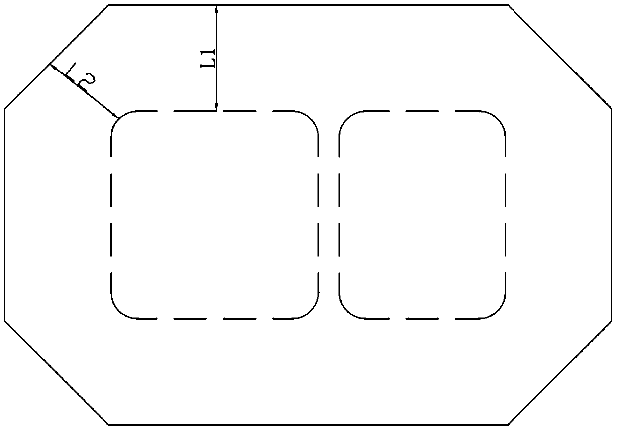
[0045] S1 Blanking: Blanking the stainless steel sheet according to the design specifications and models. While ensuring that the material on the four sides of the water tank meets the size requirements for the stretching of the water tank, the four corners of the sheet must be punched. image 3 As shown, ensure that the distance L2 from the beveled side of the blanking to the outside of the water tank after the attack angle should be less than the distance L1 from the four sides of...

Embodiment 2

[0054] The difference between embodiment 2 and embodiment 1 is that the process of forming a nano-coating in step S3 is as follows: the silicon carbide material (average particle size is 100nm) is sprayed on the surface of the water tank formed in step S2 by supersonic flame, and the stainless steel water tank base and The distance between the spray guns is 390mm, the powder feeding rate is 65g / min, and the powder feeding gas pressure is 3.8bar. Then put it into a vacuum heat treatment furnace for vacuum heat treatment, and set the vacuum degree to 3*10 -3 Pa, the heating time is 60min, heated to 1050°C, and kept at this temperature for 1.2h. The thickness of the formed nano-coating is 50 μm.

Embodiment 3

[0056] The difference between Example 3 and Example 1 is that the process of forming the fluororesin coating in step S5 is: immerse the water tank treated in step S4 in 150g / L polytetrafluoroethylene emulsion at 70°C for 50min, The water tank is placed in a vacuum heat treatment furnace, and the vacuum degree is set to 2*10 -2 Pa, the heating time is 12min, heated to 350°C, and kept at this temperature for 70min to form a PTFE coating. The formed polytetrafluoroethylene coating had a thickness of 80 μm.


PUM

PropertyMeasurementUnit
particle sizeaaaaaaaaaa
thicknessaaaaaaaaaa
thicknessaaaaaaaaaa

Abstract

The invention belongs to the field of kitchen utensils, and relates to a non-annealing integral forming process of a stainless steel water tank. The process comprises the following steps of blanking,primary molding, forming of a nano coating, secondary molding, forming of a fluororesin coating, trimming and punching. The integral forming process of the water tank can meet the quality requirementof the water tank without high-temperature annealing, reduces working procedures and improves efficiency. The nano coating and the fluororesin coating are respectively formed on the surface of the water tank through spraying or dipping in the primary forming process and the secondary forming process, and the surface performance of the water tank is greatly improved.

Description

technical field [0001] The invention belongs to the field of kitchen utensils and relates to a non-annealing integral forming process of a stainless steel water tank. Background technique [0002] At present, stainless steel sinks have single-slot, double-slot, and three-slot structures. Generally, in the manufacturing process of multi-slot (double-slot or three-slot) sinks, welding processes are generally used to weld a single formed sink into a double-slot or three-slot type. Or adopt the process of high-temperature annealing after one-time molding, and then perform secondary molding; welding increases the processing steps of the water tank, increases the cost, and the welding quality is difficult to guarantee. Welding leakage, de-soldering, and cracks are inevitable, which will inevitably affect the overall water tank. Quality and service life; and in the secondary integral molding process, the high-temperature annealing during the period also increases the production pro...

Claims


Application Information

Patent Timeline
Patent Type & Authority Applications(China)
IPC IPC(8): B21D51/18B21D35/00
CPCB21D35/002B21D51/18
Inventor 徐剑光龚镭周远明
Owner NINGBO OULIN IND CO LTD
Why Eureka
Try Eureka