Translucent electrodes based on metal nanocomposite structures
A semi-transparent electrode and composite structure technology, which is applied in the field of optoelectronics, can solve the problems of lower transmittance, achieve the effect of improving charge injection ability, better effect, and enhanced charge injection efficiency
- Summary
- Abstract
- Description
- Claims
- Application Information
AI Technical Summary
Problems solved by technology
Method used
Image
Examples
Embodiment 1
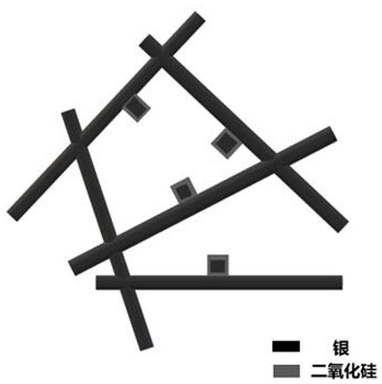
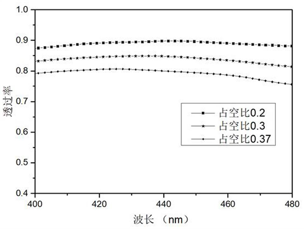
[0030] Use silver nanowires with a length of 1µm and a diameter of 30nm to form a silver nanowire electrode network, and change the duty cycle of the nanowires in the electrode network; figure 2 is the change of the silver nanowire electrode network transmittance with the duty cycle in the 400-480nm band; it can be seen that the silver nanowire electrode network transmittance increases with the decrease of the duty cycle, and the duty cycle is less than At 30%, the electrode transmittance can be basically guaranteed to be above 80%. Since the duty cycle should not be too small, the duty cycle is selected within the range of 20%-30%.
Embodiment 2
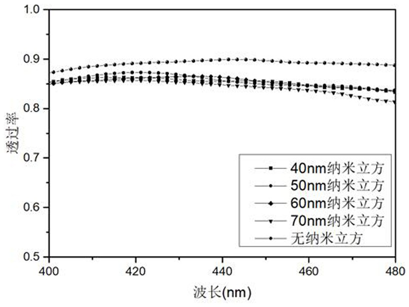
[0032] The silver nanowire electrode network with a duty ratio of 22% is added to the silver nanocube, the silver nanowire length is 1.2 µm, the diameter is 50nm, the distance between the silver nanowire and the silver nanocube is 5nm, and the silver nanocube in the electrode The coverage rate is 0.55%. image 3 In order to change the particle size of silver nanocubes, the change of silver electrode transmittance in the 400-480nm band, it can be seen that the electrode light transmittance is still above 80% after adding nanoparticles. Depend on Figure 4 It can be seen that the electric field of the silver electrode is enhanced after adding nanocubes. Nanocubes with a particle size smaller than the diameter of the nanowire have a weaker effect on enhancing the electric field; nanocubes with a particle size of 50nm and 60nm have a better effect on enhancing the electric field of the silver electrode. When the particle size increases, the nanocube enhances the electric field of...
Embodiment 3
[0034] The silver nanowire electrode network with a duty cycle of 22%, the silver nanowire length is 1.2µm, the diameter is 50nm, adding 60nm nanocubes, the coverage rate of silver nanocubes in the electrode is 0.4%. Figure 5 In order to change the distance between the silver nanocube and the nanowire, the change of the transmittance of the silver electrode in the 400-480nm band, it can be seen that the light transmittance of the silver electrode remains above 80% after changing the spacing. Depend on Image 6 It can be seen that the electric field of the silver electrode is enhanced after adding nanocubes. When the spacing is within 10nm, as the spacing increases, the electric field strength of the silver electrode also increases; when the spacing is greater than 10nm, the effect of the nanocube on the electric field enhancement of the electrode does not change much; comprehensive consideration, the spacing between the nanowire and the nanocube When it is 5-10nm, it has a b...
PUM
| Property | Measurement | Unit |
|---|---|---|
| diameter | aaaaa | aaaaa |
| diameter | aaaaa | aaaaa |
| particle diameter | aaaaa | aaaaa |
Abstract
Description
Claims
Application Information
 - R&D
- Intellectual Property
- Life Sciences
- Materials
- Tech Scout
- Unparalleled Data Quality
- Higher Quality Content
- 60% Fewer Hallucinations
Browse by: Latest US Patents, China's latest patents, Technical Efficacy Thesaurus, Application Domain, Technology Topic, Popular Technical Reports.
© 2025 PatSnap. All rights reserved.Legal|Privacy policy|Modern Slavery Act Transparency Statement|Sitemap|About US| Contact US: help@patsnap.com


