Device and method for low-cold electromagnetic semi-continuous casting
A semi-continuous, electromagnetic technology, applied in the field of metal material preparation, can solve the problems that the primary and secondary cooling cannot be adjusted independently, the difficulty of heat dissipation coordination in the height direction of the crystallizer, and the complex structure of the crystallizer, etc., to achieve easy maintenance and increase magnetic field wear The effect of penetrating depth and reducing skin effect
- Summary
- Abstract
- Description
- Claims
- Application Information
AI Technical Summary
Problems solved by technology
Method used
Image
Examples
Embodiment 1
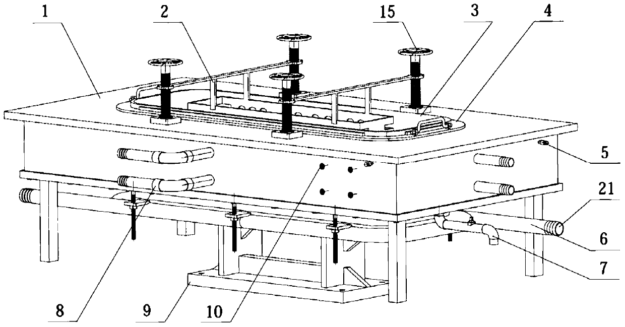
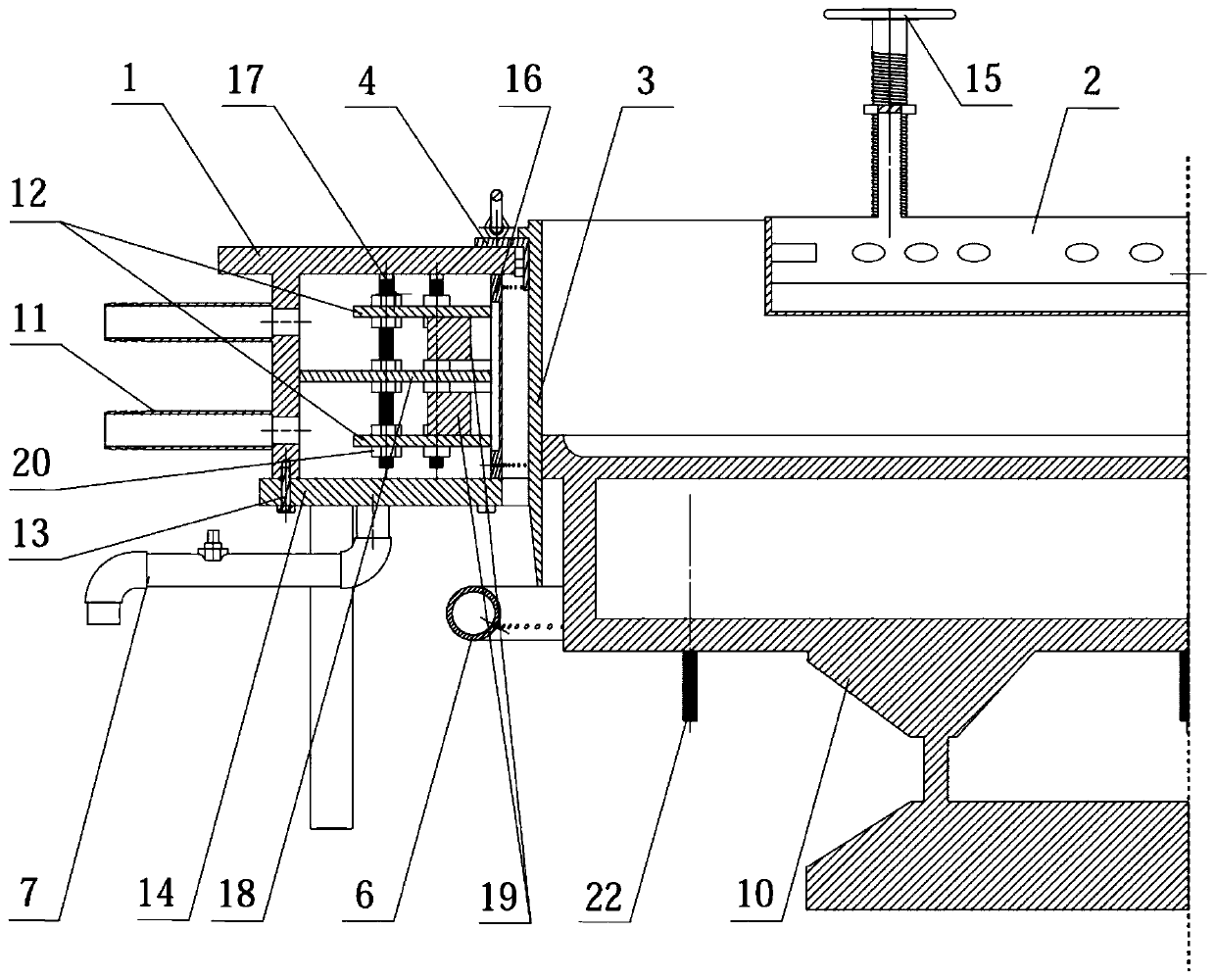
[0074] The shaft side structure of the low-cooling electromagnetic semi-continuous casting device is as follows figure 1 As shown, the cross-sectional structure is as figure 2 As shown, it includes a melt splitting device 2, a crystallizer and a dummy head 10; the outer casing 1 of the crystallizer is composed of an outer casing top plate and an outer casing side plate to form an integrated structure, and the inner casing 3 has a structure such as Figure 4 As shown, it is cylindrical and has a connection plate 23 fixed on the outer wall of the upper part, and an inner sleeve bolt hole 24 is opened below the connection plate 23 for connecting with the upper intermediate plate 4;
[0075] An upper intermediate plate 4 is provided between the top plate of the outer jacket and the inner jacket 3; the gap between the inner edge of the bottom plate 14 of the crystallizer and the outer wall of the inner jacket 2 is used as a cooling water channel;
[0076] The inner edge of the bo...
Embodiment 2
[0096] Device structure is the same as embodiment 1, and difference is:
[0097] (1) The horizontal section of the inner sleeve is circular; there is an angle of 5° between the inner wall surface of the inner sleeve and the axis, and the top cross-sectional area of the inner space of the inner sleeve is smaller than the top cross-sectional area;
[0098] (2) There is no vertical partition in the cooling water cavity;
[0099] Method is with embodiment 1, and difference is:
[0100] (1) The round ingot prepared is AZ21, with a diameter of 350mm and a length of 2500mm; the composition of the example contains Al2.5%, Zn 0.75%, Mn 0.25%, Fe<0.001%, and the rest are magnesium by mass percentage;
[0101] (2) The flow ratio of the secondary cooling water to the primary cooling water per unit time is 0.8; due to the casting of round ingots, there is no difference between wide-surface cooling water and narrow-surface cooling water;
[0102] (3) The flow ratio of the tertiary cooli...
Embodiment 3
[0105] Device structure is the same as embodiment 1, and difference is:
[0106] (1) The horizontal section of the inner sleeve is circular; there is an angle of 5° between the inner wall surface of the inner sleeve and the axis, and the top cross-sectional area of the inner space of the inner sleeve is smaller than the top cross-sectional area;
[0107] (2) There is no vertical partition in the cooling water cavity;
[0108] Method is with embodiment 1, and difference is:
[0109] (1) The round ingot prepared is ZK60, with a diameter of 400mm and a length of 2000mm; the composition of the example contains Zn5.7%, Zr0.50%, Fe<0.008%, and the rest are magnesium by mass percentage;
[0110] (2) The flow rate ratio of the secondary cooling water to the primary cooling water per unit time is 1.2; there is no difference between the wide surface cooling water and the narrow surface cooling water due to the casting of round ingots;
[0111] (3) The flow ratio of the third cooling...
PUM
| Property | Measurement | Unit |
|---|---|---|
| diameter | aaaaa | aaaaa |
| thickness | aaaaa | aaaaa |
| thickness | aaaaa | aaaaa |
Abstract
Description
Claims
Application Information
 - Generate Ideas
- Intellectual Property
- Life Sciences
- Materials
- Tech Scout
- Unparalleled Data Quality
- Higher Quality Content
- 60% Fewer Hallucinations
Browse by: Latest US Patents, China's latest patents, Technical Efficacy Thesaurus, Application Domain, Technology Topic, Popular Technical Reports.
© 2025 PatSnap. All rights reserved.Legal|Privacy policy|Modern Slavery Act Transparency Statement|Sitemap|About US| Contact US: help@patsnap.com


