
Steady-state flow test device and method for low-speed two-stroke marine diesel engine cylinder

A marine diesel engine and testing device technology, which is applied in the direction of measuring device, speed/acceleration/impact measurement, fluid velocity measurement, etc., can solve problems such as low measurement efficiency

Active Publication Date: 2019-11-01
TIANJIN UNIV
View PDF22 Cites 2 Cited by
  • Summary
  • Abstract
  • Description
  • Claims
  • Application Information

AI Technical Summary

Problems solved by technology

However, this technology is the same as the hot wire anemometer components, both of which are single-point measurement, and multi-point measurement can only be realized by constantly moving the measured point, and the measurement efficiency is low

Method used


Image

  • Steady-state flow test device and method for low-speed two-stroke marine diesel engine cylinder
  • Steady-state flow test device and method for low-speed two-stroke marine diesel engine cylinder
  • Steady-state flow test device and method for low-speed two-stroke marine diesel engine cylinder

Examples


Embodiment 1

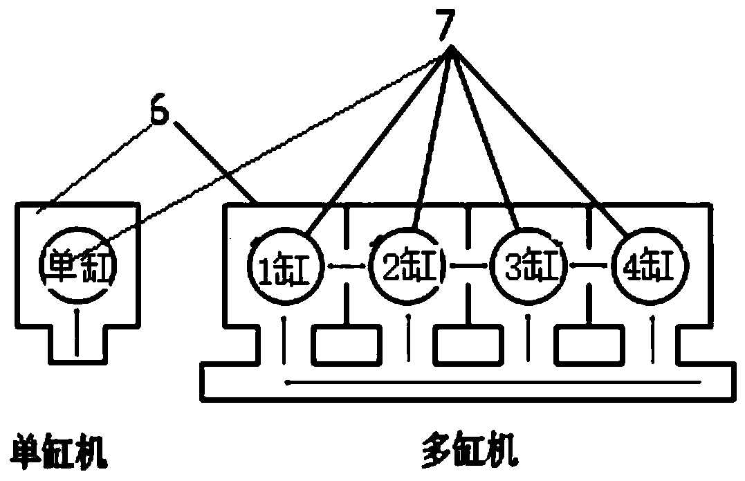
[0114] Single-cylinder machine scavenging flow test: close the valves on both sides of the scavenging box, and use the middle path to conduct a single-side air intake test. The bore is 170mm and the stroke is 850mm. The stroke is determined by the adjustment of the position of the vane anemometer assembly. Install the vane anemometer assembly, fix the vane at the stroke-to-bore ratio z / D=1.0, keep the opening of the scavenging port at 100%, and the opening of the exhaust valve at full open. Turn on the signal acquisition system, set the scavenging air pressure difference to 2000Pa, start the fan, read the eddy current speed obtained by the signal acquisition system after the air flow is stable, and then control the scavenging air pressure difference to 2000Pa, and adjust the blade by replacing the front and rear cylinder liners. The position of the anemometer assembly can be adjusted to achieve the adjustment of the stroke-to-bore ratio, so as to achieve the purpose of changing...

Embodiment 2

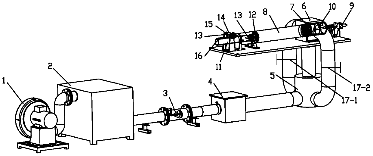
[0118] Multi-cylinder machine scavenging flow test. Such as figure 2 As shown, different from the intake mode of single-cylinder engine, the intake form of multi-cylinder engine is often double-side intake and three-side intake. The 1st and 4th cylinders in the multi-cylinder machine are double-sided air intakes. This device can open the left valve 17-1, close the right valve 17-2, and conversely open the right valve and close the left valve. Realize the same air intake method as the 1st and 4th cylinders. The second and third cylinders in the multi-cylinder engine have three-side air intake, which can be realized by opening the left and right valves at the same time. The test method of this part is the same as that of the above-mentioned single-cylinder engine.

Embodiment 3

[0120] The air enters the voltage stabilizing box through the fan, and the fan and the stabilizing box are connected with hard bent pipes and flanges. After the pressure is stabilized, the air passes through the flow meter in the pipeline and enters the mixing box, and the tracer particles (used by the PIV instrument) are introduced into the outside of the tank, and the air and the tracer particles are fully mixed and then enter the pressure stabilization cylinder. The air flows through the scavenging port into the extended cylinder liner and is discharged through the exhaust valve and the exhaust pipe. The linear motor moves by controlling the piston.

[0121] When the 3D-PIV instrument system is used for measurement, the front and rear extended cylinder liners are replaced with a complete cylinder liner, and then the PIV instrument system is calibrated, referring to Figure 6 , Figure 7. Adjust the position of the CCD camera or the lens so that the shooting plane area is...


PUM


Abstract

The invention discloses a steady-state flow test device and method for a low-speed two-stroke marine diesel engine cylinder. The composition of the test device portion lies in that a fan is connectedto a surge tank, a flow meter, a mixing tank and a pressure regulator cylinder in sequence, and the air flow can enter a scavenging box along three passages of the pressure regulator cylinder; a scavenging port is connected to an extended cylinder sleeve, a linear motor is in shaft connection to a piston, the piston is located in the extended cylinder sleeve, an exhaust pipe is sealedly connectedto the extended cylinder sleeve, and exhaust valves are located in the extended cylinder sleeve; a support stand is provided with gears and racks that constitute a transmission pair, and the gears andracks move so that the exhaust valves are located at different positions in the extended cylinder sleeve. The test method thereof comprises the steps that the laser light source is incident on the cross section of the extended cylinder sleeve, and the two cameras are placed on both sides. The speed test is divided into three steps of obtaining camera measuring parameters; eliminating image distortion; and performing three-dimensional reconstruction on the CCD camera field of view. The device can obtain the flow fields at each section by using the PIV instrument system to test, and can measurethe global velocity and eddy current intensity.

Description

technical field [0001] The invention belongs to the technical field of engine testing, and in particular relates to a cylinder flow testing device for a marine diesel engine. Background technique [0002] With the continuous improvement of the level of science and technology, the shipbuilding industry is also gradually moving towards large-scale and automation, which puts forward higher power requirements for ship propulsion devices. Low-speed two-stroke diesel engines are widely used in large civil ships due to their significant advantages such as high power, high reliability, strong durability, and good economy. Because it uses heavy oil as fuel, it will produce a large amount of harmful exhaust gas after combustion, including nitrogen oxides (NO x ), sulfur oxides (SO x ), carbon monoxide (CO), unburned hydrocarbons (HC), and particulates (PM). The scavenging process covers the entire stage from the opening of the scavenging port to the closing of the exhaust valve. T...

Claims


Application Information

Patent Timeline
IPC IPC(8): G01P5/20G01P5/06
CPCG01P5/06G01P5/20
Inventor 王天友鲁祯张备孙凯高玉川
Owner TIANJIN UNIV
Learn More