
Power supply unit and rotary electric machine

A technology of power supply unit and electrical connection, which is applied to electrical components, electromechanical devices, electrical components, etc., can solve the problems of difficulty in improving the positional accuracy of the top part of the terminal and significant thermal deformation of resin.

Inactive Publication Date: 2019-10-25
HONDA MOTOR CO LTD +1
View PDF3 Cites 0 Cited by
  • Summary
  • Abstract
  • Description
  • Claims
  • Application Information

AI Technical Summary

Problems solved by technology

[0008] However, in the power supply unit of Patent Document 1, there is a problem that thermal deformation of the resin is significant during molding, and it is difficult to improve the positional accuracy of the terminal tip portion.

Method used


Image

  • Power supply unit and rotary electric machine
  • Power supply unit and rotary electric machine
  • Power supply unit and rotary electric machine

Examples


Embodiment Construction

[0023] One embodiment of the present invention will be described in detail with reference to the drawings. In addition, in the description, the same symbols are assigned to the same constituent elements, and overlapping descriptions are omitted.

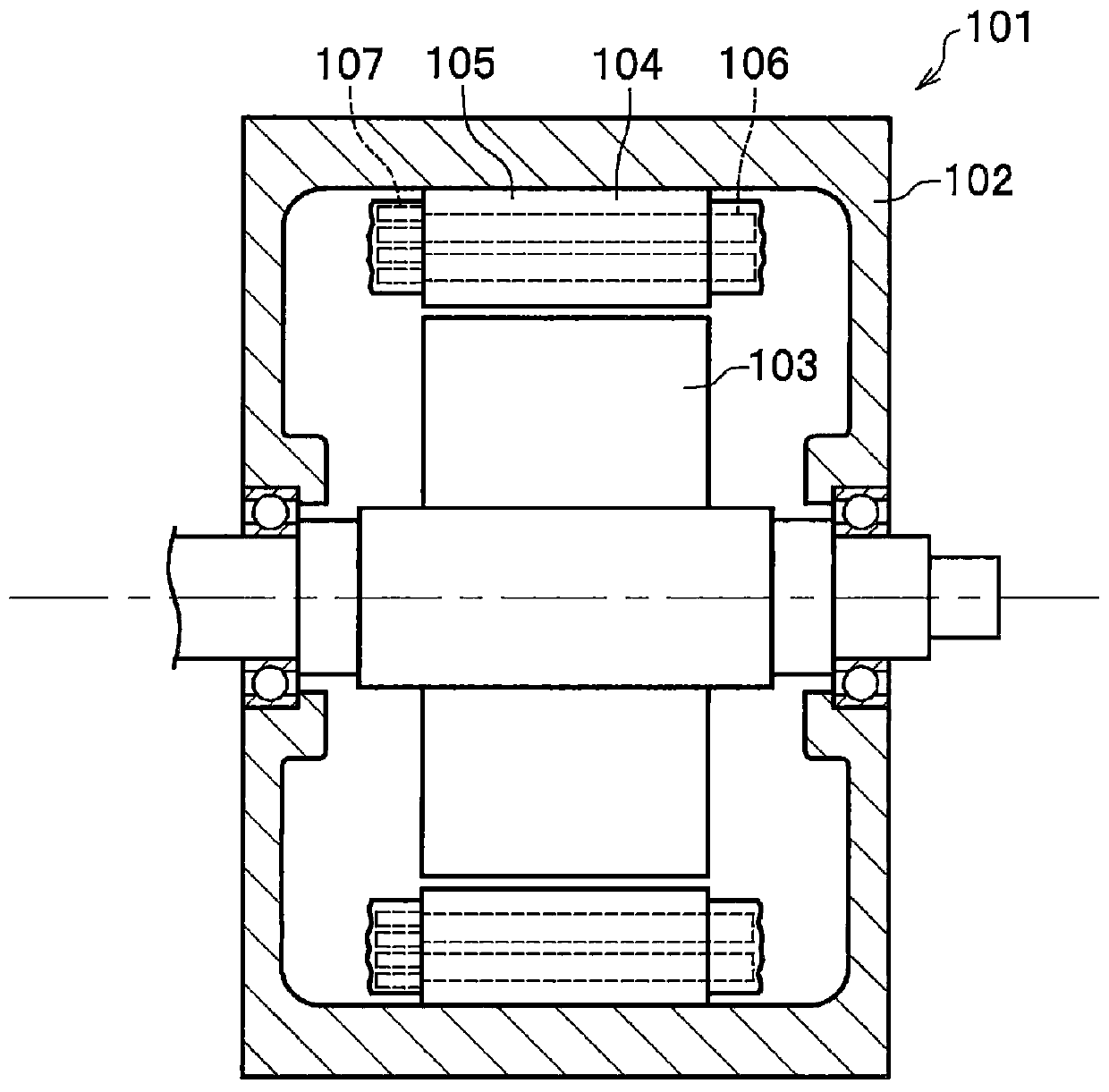
[0024] figure 1 It is a schematic configuration diagram (sectional view) showing the overall configuration of the rotating electric machine 101 including the power supply unit according to the present embodiment. The rotating electrical machine 101 is mounted on vehicles such as a hybrid car or an electric car, for example, and functions as a running motor when electric power is supplied from the outside, and as a generator during regenerative braking.

[0025] In addition, the power supply unit of the present invention is not limited to the rotary electric machine 101 for vehicles, but can also be applied to stationary motors, motors for other uses, and generators.

[0026] In addition, the up and down in the description means the...


PUM


Abstract

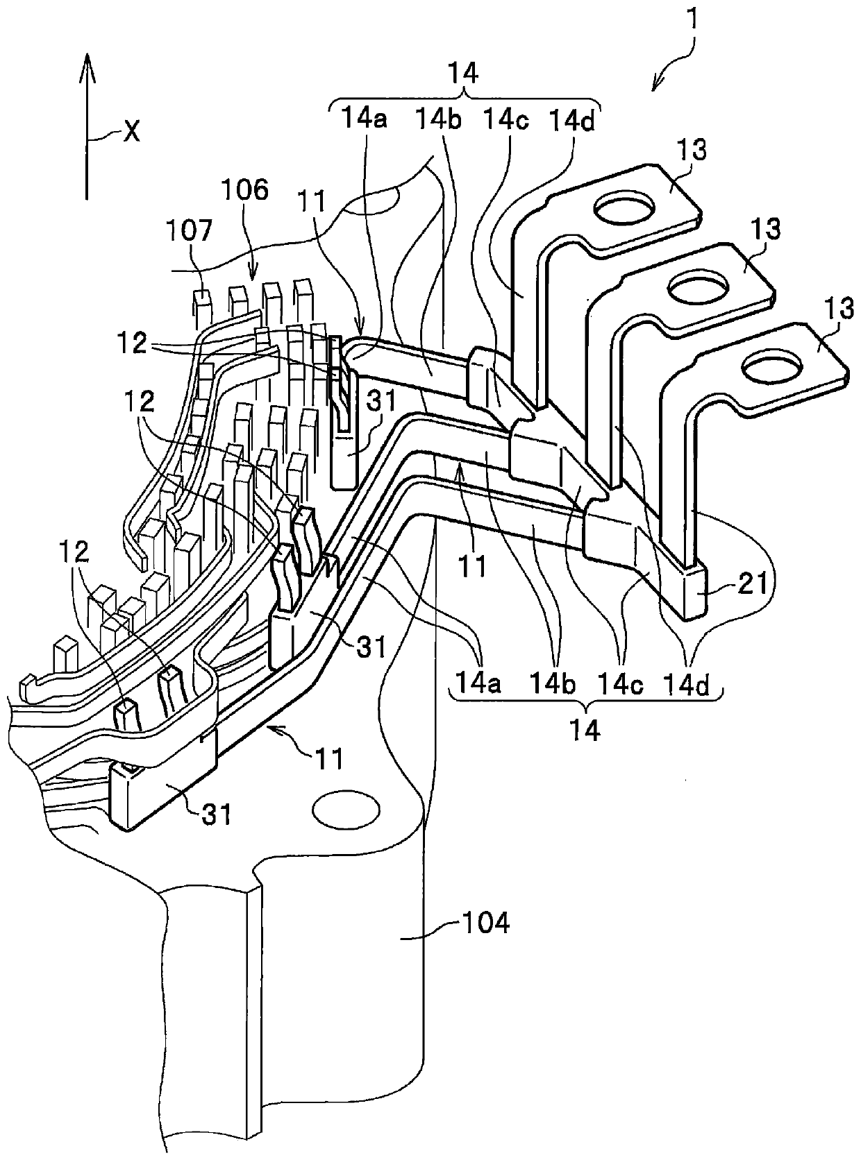
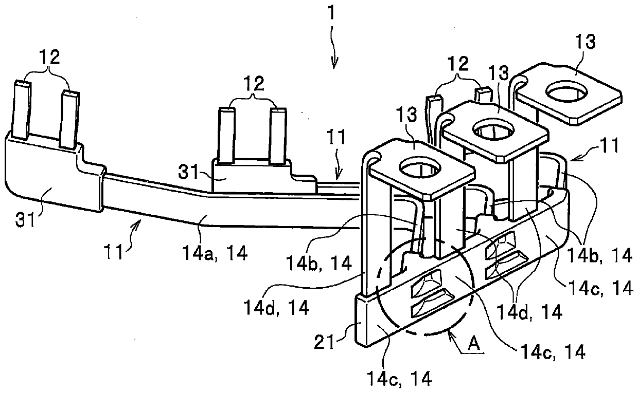
Provided are a power supply unit and a rotary electric machine. A power supply unit (1) comprises: a plurality of power supply bodies (11) electrically connecting to each of conductors (107) constituting a coil (106) wound for each of a plurality of phases; and a resin holding part (21) formed of a resin material and integrally connecting and holding the plurality of power supply bodies (11). Theresin holding part (21) of the power supply unit is provided with: outside protection sections (22) surrounding the power supply bodies (11); and a connection section (23) connecting two adjacent outside protection sections (22). The power supply unit makes it possible to reduce the influence of thermal stress by setting a thickness dimension L (23) of the connection section (23) to be the same asa thickness dimension L (22) of the outside protection sections (22).

Description

technical field [0001] The present invention relates to a power supply unit for connecting coils of each phase of a rotating electric machine to the outside, and a rotating electric machine having the power supply unit. Background technique [0002] In a rotating electrical machine, lead wires are connected to the coils of each phase, and electric power is supplied and received (electric power transmission) between the outside and the coils of each phase through the lead wires. [0003] For example, Patent Document 1 discloses a structure in which corresponding lead wires are integrated with each other by insert molding. [0004] [Prior Art Literature] [0005] 【Patent Literature】 [0006] Patent Document 1: Japanese Invention Patent Laid-Open Publication No. 2015-133873 Contents of the invention [0007] 【Technical problem to be solved by the invention】 [0008] However, in the power supply unit of Patent Document 1, there is a problem that thermal deformation of the ...

Claims


Application Information

Patent Timeline
Patent Type & Authority Applications(China)
IPC IPC(8): H02K5/22H02K3/50
CPCH02K3/50H02K2203/09
Inventor 大澄优辅赤泽圭铃木正义
Owner HONDA MOTOR CO LTD
Learn More