


Quick Research
Generate reliable direction feasibility study reports for your R&D in just a few steps.

Technical Q&A
Discover and master advanced knowledge NOW. Basics, ideas, possibilities, all at once.

Find Solutions
As an expert in R&D theories, this can generate solutions to your technical problems instantly.

Evaluate Feasibility
Analyze your overall solution with one click, know your potential R&D risks in advance.

Monitor Landscape
Get weekly tech updates, stay abreast of the latest tech innovations and key insights.
Cell separation system and method thereof
A separation system and cell technology, applied in the field of cell separation, can solve the problems of high cost, high difficulty in implementation, and high cost, and achieve the effects of ensuring separation quality, reducing complexity, and controlling use costs
- Summary
- Abstract
- Description
- Claims
- Application Information
AI Technical Summary
Problems solved by technology
Method used
Image

Examples
Embodiment 1
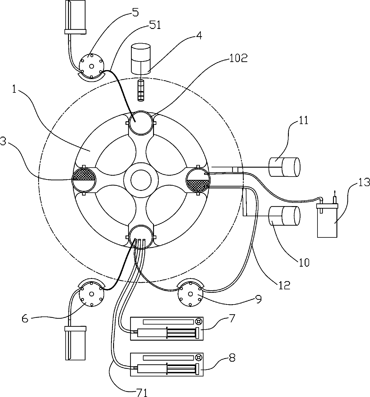
[0055] partial reference figure 1 , a cell separation system comprising:
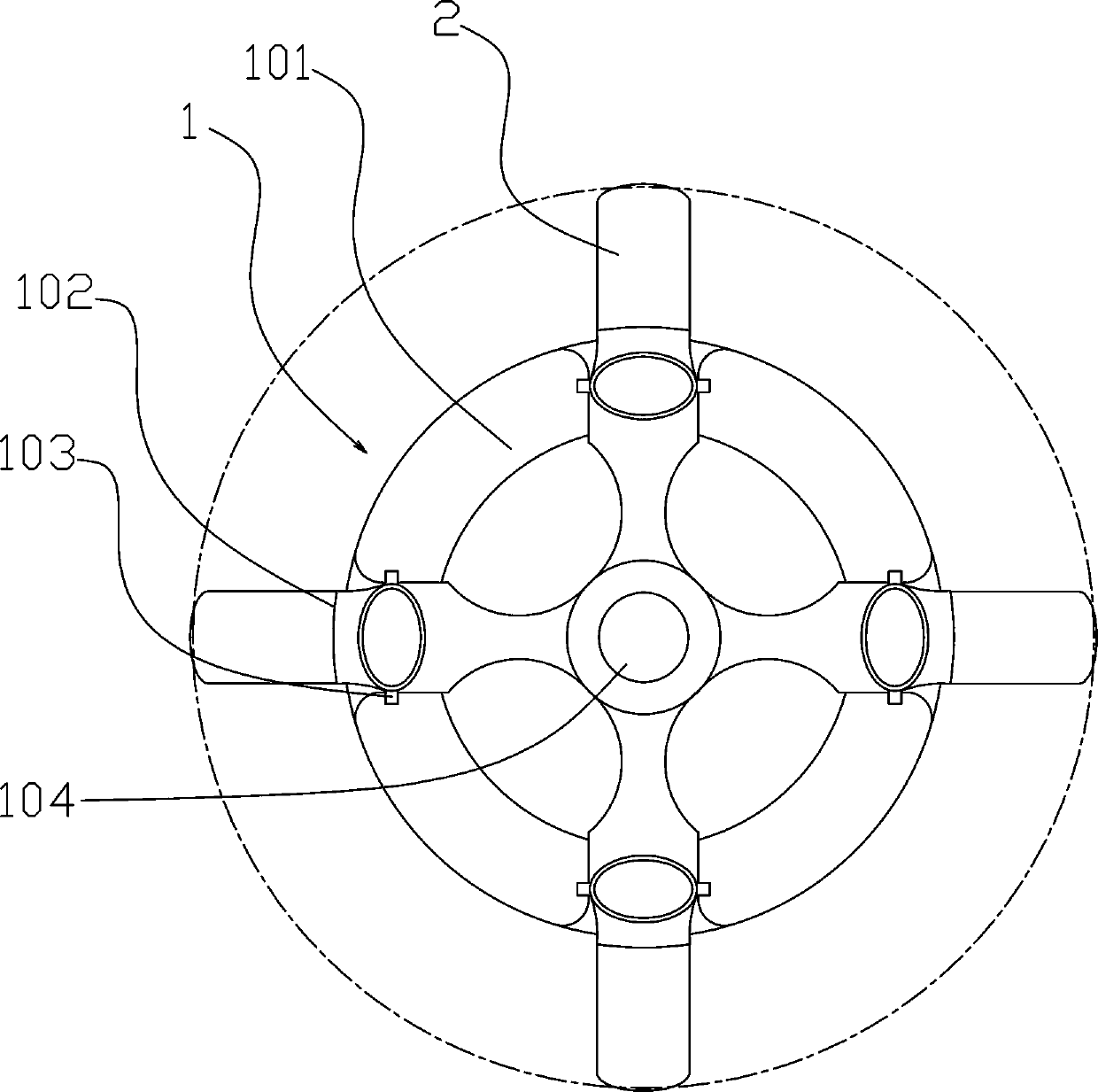
[0056] Centrifugal device 1, centrifugal device 1 is provided with substantially horizontal centrifugal frame 101, and centrifugal frame 101 is connected with centrifugal motor 105, and drives centrifugal frame 101 to rotate, and centrifugal frame 101 is provided with the tube base 3 that is used to place centrifuge tube 2, so that The liquid in the centrifuge tube 2 is centrifuged; the centrifuge device 1 is provided with a corner positioning device, which is used to stop the tube base 3 at a preset circumferential position;
[0057] At least one liquid adding device, the liquid adding device is provided with a pump for injecting preset liquid into the centrifuge tube 2; for example, adding tissue cell cleaning solution and tissue disinfectant;
[0058] At least one accurate liquid addition device is provided with a screw injection device, a peristaltic pump or a diaphragm pump to achieve accurate liq...
Embodiment 2
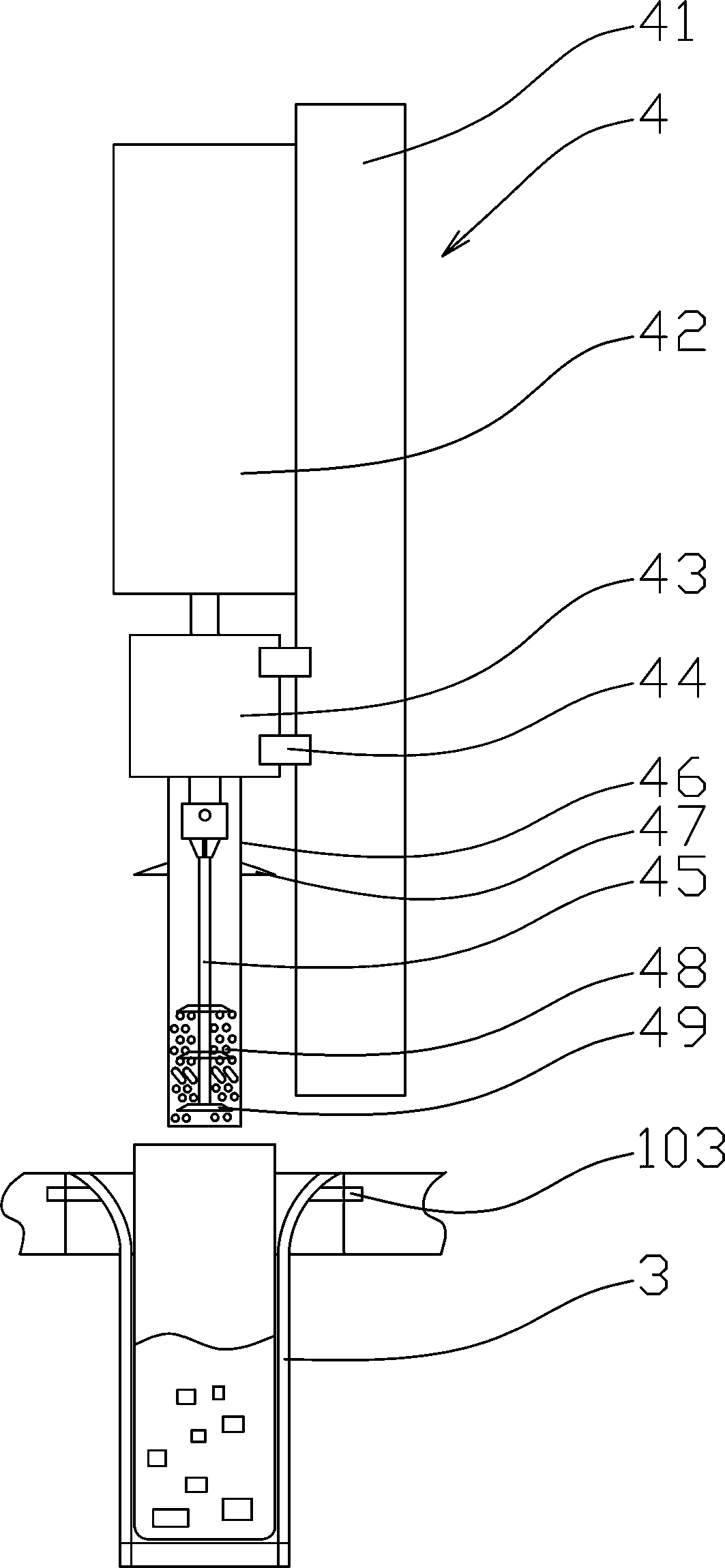
[0063] On the basis of Example 1, the preferred scheme can be found in figure 1 and image 3 Among them, a crushing device 4 is also provided above the centrifugal frame 101. In the crushing device 4, the lifting device is connected to the crushing motor 43, and the shaft of the crushing motor 43 is fixedly connected to the cutter bar 45, such as through a drill bit clamping mechanism. , through tapered hole or rectangular hole, hexagonal hole cooperates magnet to connect, be provided with at least one crushing blade 49 on the cutter bar 45, preferably arrange a plurality of crushing blades 49 on the cutter bar 45 in this example, on the cutter bar 45 The outer ring is fixed with a non-rotating crushing sleeve 46 . Preferably, the crushing sleeve 46 is fixedly connected to the housing of the crushing motor 43 , for example snap-fitted. The crushing sleeve 46 is provided with a plurality of through holes 48, including round holes or slotted holes;
[0064] The lifting device...
Embodiment 3
[0080] On the basis of Example 2, the preferred scheme is as figure 1 , 5Among them, a suction and filling device 9 is also provided. The structure of the suction and filling device 9 is: one end of the suction and filling pipe 12 is fixedly connected with the suction lifting mechanism, and the end is located on the centrifuge tube 2 placed on the centrifuge frame 101. When the suction filling pipe 12 is lowered, the bottom is located in the position near the bottom of the tube in the centrifuge tube 2. When the suction filling pipe 12 rises, the bottom of the suction filling pipe 12 is higher than the bottom of the centrifuge tube 2. Nozzle;
[0081] The suction lifting mechanism is a screw nut mechanism driven by a motor, a rack and pinion mechanism, a belt mechanism or a crank slider mechanism, or the suction lifting mechanism is a slider mechanism driven by a linear motor, or the suction lifting mechanism is compressed air driven cylinder;
[0082] The other end of the ...
PUM
| Property | Measurement | Unit |
|---|---|---|
| recovery rate | aaaaa | aaaaa |
Abstract
Description
Claims
Application Information
 - R&D Engineer
- R&D Manager
- IP Professional
- Industry Leading Data Capabilities
- Powerful AI technology
- Patent DNA Extraction
Browse by: Latest US Patents, China's latest patents, Technical Efficacy Thesaurus, Application Domain, Technology Topic, Popular Technical Reports.
© 2024 PatSnap. All rights reserved.Legal|Privacy policy|Modern Slavery Act Transparency Statement|Sitemap|About US| Contact US: help@patsnap.com